Continue to Site

Eng-Tips is the largest engineering community on the Internet

Intelligent Work Forums for Engineering Professionals

  • Congratulations waross on being selected by the Eng-Tips community for having the most helpful posts in the forums last week. Way to Go!

Glue Contact 1

Status
Not open for further replies.

sushi75

New member
Mar 11, 2015
84
GB
Hello,

I have a solid geometry that I would need to include in an existing model mesh with solid elements. As it required to connect TET and HEX, it seems that the best option is to create a glue connexion between those solids.

I'm not familiar with this femap capability, so I'm trying on a simple example, shown in the picture attached. It's basically a cube and a plate that I would like to link.

I have created a glue contact between them, but I was expecting that it would form a single solid, but looking at the deformed shape, it is still 2 independant bodies.

Hope someone can bring me with some directions; maybe there is something I should do in the analysis deck??

Thanks a lot for your help!!

 
 http://files.engineering.com/getfile.aspx?folder=43e65302-5df6-4c08-b15a-835b3fc054b8&file=glue.bmp
Replies continue below

Recommended for you

Hey man,
Just grab your surface & solid geometry and "Non-Manifold Add." This associates the surface and solid together.
Then, set your meshing attributes for the cube and surface, let'er rip. Might need to merge nodes along surf/solid intersection.

Don't even mess with the contact parameters, please. You are about to get in way over your head...
If you REALLY NEED to use contacts, I can still help. Try to keep it simple first.

Happy meshing
KZ
 
Dear Tom,
You need to define a GLUE edge-to-face connectior with two regions: one EDGE region (the SOURCE) and other the SURFACE region (the target).

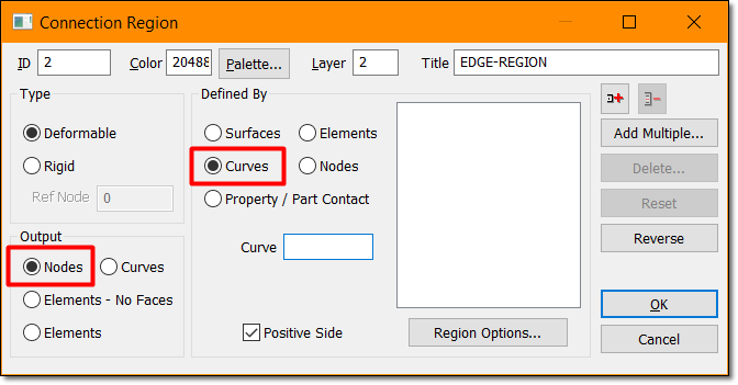
• The source EDGE region should be defined by PICKING THE CURVE(S), and selecting NODES as ouput. Edge regions are edges of the shell elements CTRIA3, CTRIA6, CTRIAR, CQUAD4, CQUAD8,and CQUADR.

EDGE-REGION_ez9eqq.png


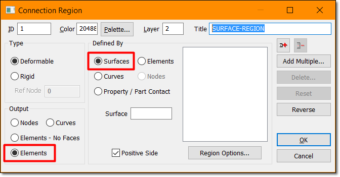
• The TARGET SURFACE region should be defined picking surfaces in the screen, and as OUTPUT select ELEMENTS (this is the default option). Surface regions are the faces of the shell elements CTRIA3, CTRIA6, CTRIAR, CQUAD4, CQUAD8, CQUADR and the faces of the solid elements CHEXA, CPENTA, CPYRAM, and CTETRA.

SURFACE-REGION_wgq9lf.png


Next define the CONNECTOR with care: the TARGET region should be the surface region, and the SOURCE region should be the EDGE region.

And define the GLUE property: click in defaults to enter the correct options, the important one is the separation (distance) between SOURCE & TARGET regions.

And you are done, please note that miracles don't exist, do not use a GLUE contact where a high stress gradient exist, use it in zones of the model where the response is costant, OK?.

Glue with FEMAP & NX NASTRAN is a simple and effective method to join meshes which are dissimilar. It correctly transfers displacement and loads resulting in an accurate strain and stress condition at the interface. The grid points on glued edges and surfaces do not need to be coincident. Glue creates stiff springs or a weld like connection to prevent relative motion in all directions.

A simplistic description of edge-to-surface glue is that the software creates pseudo-faces along the edges in the source region. It then connects these pseudo-faces to the shell or solid faces in the target region with weld like connections. From the glue points on the source side pseudo-face, the software projects a normal in the outward normal direction. In addition, the software searches a small distance in the inward normal direction in order to glue edges and surfaces that may interfere due to meshing irregularities.

A glue connection occurs when the following is satisfied.
A. When a projected normal hits the face on the target side.
B. The distance between the two is equal to or less than the search distance which you specify for the glue pair on the BGSET entry.

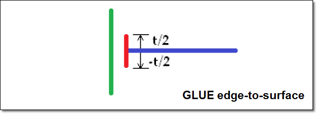
For example, the green line below represents shell or solid free faces in a target region, the blue line represents shell elements, and the red line represents an internally created pseudo-face along the
edges in the source region. The pseudo-face can be visualized by extruding the element edge from -t/2 to +t/2 in the parent shell element normal direction.

glue-edge-to-surface-detail_kbstjj.png


Best regards,
Blas.

~~~~~~~~~~~~~~~~~~~~~~
Blas Molero Hidalgo
Ingeniero Industrial
Director

IBERISA
48004 BILBAO (SPAIN)
WEB: Blog de FEMAP & NX Nastran:
 
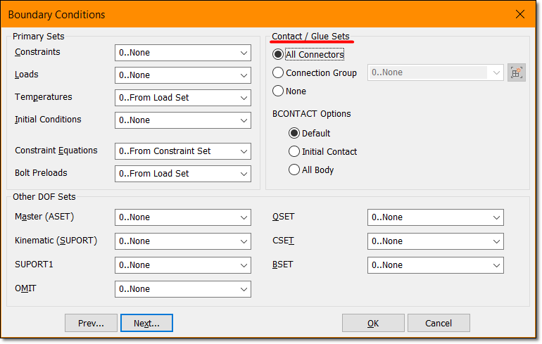
Thanks Blas, once again your help is very useful! I manage to create the connection as described in you reply, but as I'm running MD nastran, I had to build manually the glue connection in the input file with the BCONNECT.

So it works, but not as expected!!
 
tomstress - I also use the Femap/MD Nastran configuration. It is rumored that Femap 11.2 will handle glued contact for us correctly now, but I have not confirmed.

________________________
FEMAP v11.1.0
MSC Nastran v2013
 
Hello!,
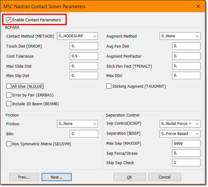
In fact, not a rmor, is real!!. Starting from FEMAP V11.2 (March 2015) it was added the MSC Nastran Contact Solver Parameters dialog box to Analysis Set Manager for Static analysis.

The MSC Nastran Contact Solver Parameters dialog box contains a number of options which can be specified when performing an analysis in MSC Nastran, which also includes surface-to-surface contact. All of the items in this dialog box correspond to items (Params) which can be included on the BCPARA entry. For more information, see the BCPARA (Contact Parameters - SOLs 101 and 400) entry in the MSC Nastran Quick Reference Guide.

You must check the “Enable Contact Parameters” box for FEMAP to use any options in this dialog box:

msc-nastran-contact_xz9qub.png


~~~~~~~~~~~~~~~~~~~~~~
Blas Molero Hidalgo
Ingeniero Industrial
Director

IBERISA
48004 BILBAO (SPAIN)
WEB: Blog de FEMAP & NX Nastran:
 
Goods news then!

Meanwhile I create this connection by hand on Nastran. I'm just a bit puzzled about a model I'm running. If I have solid elements intersecting, and I create a glue connection between them (considering I have 2 different typeo of elements; tet and tria).

My question is fairly simple, does this model really reflect reality as I wonder if these elements "overlapping" each other do not add extra stiffness?? In that case the stress prediction might be wrong I guess.

Thanks for your help, (can't wait for the new release of femap!!)
 
In my opinion overlapping elements will not add extra stiffness. They may generate extra enormous stress as Nastran will see one face pressed into the second.
 
Status
Not open for further replies.

Part and Inventory Search

Sponsor