Continue to Site

Eng-Tips is the largest engineering community on the Internet

Intelligent Work Forums for Engineering Professionals

  • Congratulations waross on being selected by the Eng-Tips community for having the most helpful posts in the forums last week. Way to Go!

Glulam bridge lateral torsional buckling analysis 4

Status
Not open for further replies.

molibden

Structural
Apr 11, 2010
200
I have an interesting pedestrian bridge I might design. It is similar structure like this one.

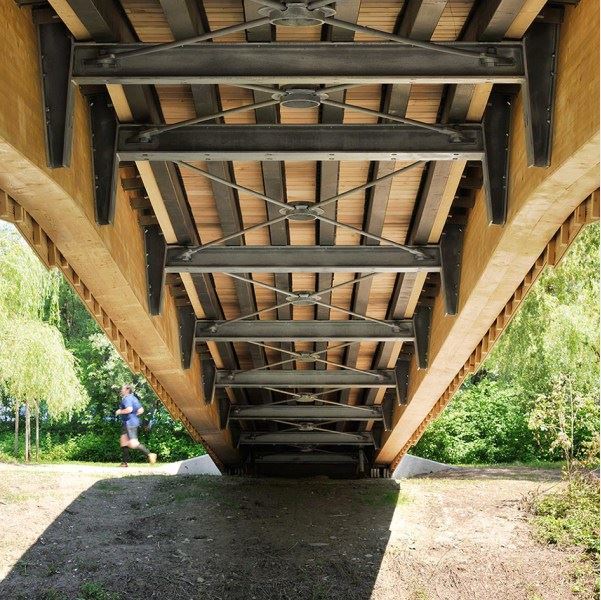
It consists of two main glulam beams, connected with steel U-frames at 4 meters. Glulam beams are a bit tilted outwards, making kind of a V-shape (steel frames follow this shape). Main glulam beams are asymetrically pitched cambered, simply supported, span is 40m. Width of the bridge is approx. 3 m. There is steel bracing beneath the deck between the U-frames.

My main concern is lateral torsional stability of the main beams as they are laterally supported with rather elastic steel frames and tilted outwards. I figured I would model the beams in FEM software with surface elements and steel with line elements. Then I would do a nonlinear stability analysis to see how the beams buckle. Then I would use effective length between buckles to design per code (Eurocodes). I have limited experience with nonlinear analysis (or linear buckling analysis for that matter) so any guidance for design process including stability would be very welcome.
 
Replies continue below

Recommended for you

You will need some heavy frames at the end to restrain the beams from rotation. AITC has pretty clear strength reduction factors for lateral bracing. Don't know about Eurocodes!

I would beef up the steel frames and make a laminated wood deck to provide lateral resistance. For conservative value, brace forces = 2% of flange force. With your beams already rolled out of vertical, not sure how to handle.

 
Thank you all for your input. I will answer also to members from other thread.

Glulams are over 2 meters in height at mid-span and they will be visible from outside so kind of hard to replace with steel. Essentially steel beams or trusses would have same problem, as we need to support top flange in compression with cross U-frames. You can see this kind of structure here.

Because my geometry is complex, I know I need to do FE model with glulams and steel frames and check global buckling. X-bracing is important of course but my main concern is lateral stability of glulams.

I am not sure how to use code related reduction factors for lateral buckling of the glulams, as my supports aren't 100% rigid (more like beam on elastic supports). One option is to beef up steel frames, load them with all loads plus brace forces and limit lateral deflection. Then I could presume rigid supports to design glulams.

I could also do non-linear analysis (geometry) but my experience with using those results is limited so I am not sure I should go this way.
 
Interesting project! I will say that the steel u-frames in the example you showed me don't seem to be very stocky at a quick glance, although I can't exactly claim to be a timber half-through bridge specialist!

I had a quick look at EN 1995-1-1 which gives some provisions for LTB. Its interesting to note that the code advocates an effective length based approach like BS5400 did; this is in comparison to EN 1993 which requires the designer to calculate Mcr him/herself.

I'd need to see a bit more of the actual bridge (especially in plan, as well as a cross-section showing how composite action is achieved between the many layers of beams) before offering anything. However I think I would use the following approach as a starter for ten to determine the sensitivity of the structure to LTB, let alone any nonlinear buckling analyses!

1. Set up a quick 2D plane-frame model of the u-frames using LUSAS/whatever in-house FE program your office has. Apply a unit load of 1kN at the top of the u-frames and determine the associated lateral deflection. You can then work out an appropriate spring stiffness, which represents the discrete lateral restraint offered by the u-frames.

2. Create a simple 2D line beam model representing the bending stiffness of the timber girders about their minor axis. Add supports representing the spring stiffness calculated in the 2D plane-frame model at the spacing of the u-frames. Apply a unit load at both ends and do a quick linear eigenvalue buckling analysis to calculate the load factor at which the beams will buckle. You can then back-calculate an appropriate effective length from the Euler buckling equation. From previous experience (with steel bridges mind) its usually of the order of Lw/3 but I would not be surprised if its less than this due to how slender the u-frames seem.

I'd definitely head down that approach before going down any nonlinear analyses or shell element exercises. FEA in timber is often a very different beast as its an orthotropic material. It might be worth giving Trada a call; I've found them very helpful in the past even though my company arent actually a member. I'd also give some thought to composite action between the glulams; theres an Annex in the back of EN 1995-1-1 which gives a means of properly allowing for the degree of composite action between all the glulam beams.

I think overall this problem requires a bit of research and thinking about especially if you have relatively little experience in timber construction; at tender stage though I think the u-frame approach I listed above is a good place to find your feet.

Hope some of this helps, good luck!


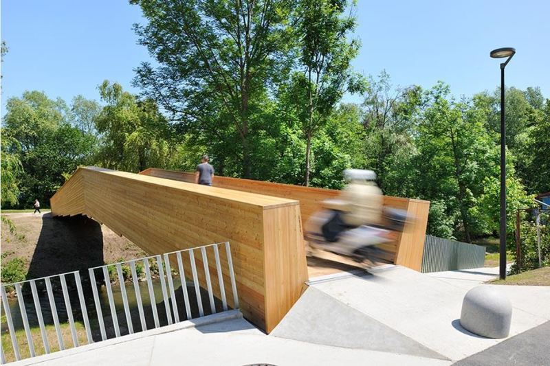
Just an update. This is completed bridge.

glulam_bridge1_mkvc9z.jpg


glulam_bridge2_tfdfbx.jpg
 
Status
Not open for further replies.

Part and Inventory Search

Sponsor