Eng-Tips is the largest engineering community on the Internet

Intelligent Work Forums for Engineering Professionals

Good GD&T representation

Status
Not open for further replies.

Bogdan.

Mechanical
Dec 18, 2019
9
0
0
DE
Hello guys,

Please can you advice me if the datums and deviations are correctly noted on the 2D ?

Thank you in advance.

test_veueag.jpg
 
Replies continue below

Recommended for you

Shouldn't the size dimension of datum feature A have a tolerance like the size dimension of datum feature C?
IMHP, geometrical tolerancing for the upper end surface is not so clear.
Position of upper end surface is controlled with regard to datum features A and B. But, datum features A and B leave movement in the axis-direction of datum feature A unconstrained, which means the origin is not defined, nor the nominal location of surface from the origin.

Woosang
 
Hello Woosang,

Thank you very much for your answer.
I don't understand exactly what do you mean, please can you make on my image the corrections?

Thank you
 
Bogdan P,

Could you give us more details about what this "duct" suppose to do/ assembled? More details about the functionality of this part.
We know it is an ISO drawing, and based only on the syntax looks okay. Again, syntax only.

Is this an assembly? So the GD&T is for an assembly level drawing?
What is the tolerance for datum feature A? How big/small this feature can be?

I guess, bottom line, more details are needed.

 
Bogdan. P

My English is not good enough. One more try…

If you want to give position tolerance to a feature, nominal position (or true position) of the feature should be defined.
Usually this will be done by datum features with basic dimensions from them to a controlled feature.
If your part (or assembly) is defined with associated 3D model which is authorized for manufacturing and inspection, the 3D model itself can be basic as well. I assume that you have 3D model of this part.

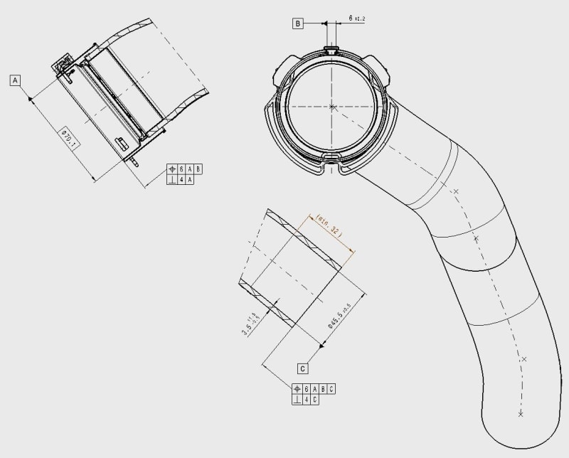
Have a look at the datum reference frame A|B|C at lower portion. DRF A|B|C fully constrains the part.
The part is positioned and oriented to the DRF, and 3D model gives basic location of the controlled feature within the DRF, so you can inspect the position according to your drawing.

But, DRF A|B at the upper portion does not fully constrain your part.
Full constraint is not always necessary but in this case remaining degree of freedom in the direction of datum axis A should be fixed.
Maybe if you change A|B to A|B|C it can be measureable.

By the way, how does datum feature B look like?
 
Status
Not open for further replies.
Back
Top