Continue to Site

Eng-Tips is the largest engineering community on the Internet

Intelligent Work Forums for Engineering Professionals

  • Congratulations IDS on being selected by the Eng-Tips community for having the most helpful posts in the forums last week. Way to Go!

Gorman-Rupp S8D1-E275 in Series? 5

Status
Not open for further replies.

kkribs

Mechanical
Jun 8, 2015
5
Just posted this in another forum. I think this is the right one...

I'd like to ask if anyone here has staged a Gorman-Rupp S-Series S8D1-E275 in series?

We don't recommend it here in Canada and I'm wondering if anyone has tried it and the result. We have an open pit mine, lifting a total of 475 ft, with HDPE 12" thick-wall and SCH40 steel along the pipeline. Also header and main at 200 ft. elevation from water table. 1750 gpm merging with a symmetrical system to get to 3500 total gpm. With volatile voltage, common in remote mines, this 275 hp, double impeller design is very sensitive to back pressure and causes much turbulence, perhaps figuratively and literally ;).


Much appreciated if anyone happens to have experience.

Thanks,

Kyle Kirby
Gorman-Rupp Canada
 
Replies continue below

Recommended for you

Lets get the picture right first

We have 2 parallel runs of these pumps, with 2 pumps in series in each run, with each pump run pushing 1750gpm at a total developed head of 475ft ( i.e 240ft approx at 1750gpm per pump)? If so, it doesnt match up with the pump curve. Both pumps running fixed speed ? How do you enable capacity or pressure control?

Pump curve also doesnt show NPSHr, but would suspect it is significant.

Is this more a power supply stability issue here - pump trip on high amps during voltage dips ? if so, electrical details would be more relevant. Once that is resolved, NPSHr for second pump would be adequate?
 
From all I can see on the GR website, these are submersibles - so how do you wire these up in series?
 
It's not easy to work out what is happening, what your problem is and why you want to double up these pumps.

If you can post a sketch showing this in section with heights, pipe size, flows etc

From my reading of this you have a total lift height from the bottom of your mine of 475 ft. At about the 200ft mark from the bottom, two of the pumps are then manifolded together with then one? larger pipe from this level to the top?

The issue as I see it is that you have a large static head which you need to reach before you get any flow and then need to add on your frictional losses. My guess is that when running you pump is hence putting out more than 475 ft - maybe 550 to 600?? When two pumps are running this n one value, when one stops or trips the head required reduces a bit due to less friction in the common pipe, the flow increase and hence your power goes up. If you've got less volts due to a poor electrical system then your amps will go up for the same power.

adding two pumps in series will lower the head of each to possibly somewhere in the 300- 350 area??, but generate more flow and hence more power.

You need to work out your system curve before you can decide anything else.

Remember - More details = better answers
Also: If you get a response it's polite to respond to it.
 
Thanks guys!

I'm pretty comfortable with doing all of the system analysis and system curves, etc. I have created a system curve. My program is pretty sweet, haha! The question is really asking if anyone has run them in series before. I don't expect anyone has. The chances are very low, but I thought I'd get started on this forum since it can be great teaching and learning tool.

Also, not sure if you're familiar, but I also need to account for suction pressure on submersible 2 of about 20 PSI is a good number to shoot for. Without enough suction pressure, as submersible 1 wears, the close tolerance 'gap' increases and more recirculation occurs. With more recirculation, the performance curve drops (pressure drop, vertically on curve). With too little suction pressure for sub 2 after a bunch of wear, you run into an issue of sub 2 creating a vacuum since sub 1 can only lift so much now (plus friction losses), and the result is damaging.

George, yes the issue is power and voltage. They run amazing by themselves, but an analogy would be that they're twin brothers and don't get along. If the bottom bunk submersible feels some inconsistent power, he'll beat the shit out of his brother. That analogy turned out pretty funny... FUCKIN' NERD!

NPSH isn't very relevant as it will be flooded suction. Chances of cavitation are quite low, unless suction pressure to sub 2 gets too low, then sub 2 could cavitate, eventually. Since these pumps are running in the middle of the curve, NPSH usually is pretty favorable. Many people forget to account for it and they push for full curve flow.

On the topic of NPSH, it's an interesting concept that took me a while to get in my head. Pumps need atmospheric pressure to push down on the water and thus push up the fluid as their is a differential pressure created by the self-primer (or vac-assist, whatevs). This is usually only relevant when there is a suction lift. The more lift, the more the atmosphere has to push down the fluid to get the system dynamic. Picture boiling water. It's already vaporizing. You now have to account for that reduction in the ratio of water to air. Cavitation is actually water vapor turning back into water. This state change causes a crazy amount of force on the impeller. I often see impellers that get destroyed because no one accounted for NPSH and they tried to run it too fast.

Many people don't realize that submersibles can be run in series just like any self-priming centrifugal pump. I was just talking to a colleague and they can just tilt them on their side. They have connections that allow you to run your suction pipe straight into it.

Cheers!

Kyle


"First principles thinking"
Elon Musk
 
Weird timing, as of 4:30 last evening I was handed a G-R drawing of two submersibles in series (two sets actually).They are sewage, 100 GPM at 95’ each pump or 100 GPM at 190’ per set. They are across the line starting, with one wet and one dry. They have been installed for 14 years and we have been asked to recommend some replacement pumps, as G-R no longer offers these pumps. Looking at the design calcs, NPSH is not a problem. Talking to the operator he said there has never been a problem but he thinks the pumps are “tired”. I think impellor wear, but who knows? My only worry is the case pressure on the higher pump. I have done this in the past, but used submersible first stage and vertical dry-pit as the second. Always used mechanical seals, never had a problem.
Steve
 
Check if a pressurised bladder vessel between sub1 and sub2 will help to tide over these voltage dips.
 
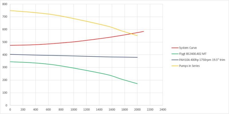
FYI, we're going with a sub at the bottom (turns out they already have a Flygt sub in place for the low pump), and a centrifugal skid-based GR Prime-Aire+ series pump at 100' elevation. at 200' elevation like the engineer designed, there isn't enough suction pressure to feed pump 2. At 100', it's just riiiight, just like my porridge.

Here's my graph if anyone is interested. I've trimmed the impeller to overshoot the flow they want. They can trim it down if they end up needing less flow, but for mine-dewatering, I can't see them wanting less. x-axis is flow (usgpm) and y-axis is pressure (feet of head). FYI, the graph below has only partial pump curves. Just so you know there is more to the right.

graph_fjt5lf.jpg


Thanks George, I'll check out that bladder vessel you're talking about for interest sake. If you have a quick link, feel free to send it to me.

Kyle

"First principles thinking"
Elon Musk
 
Do not fall into the trap of locating the second pump to far up the gradient, it should be well below, so that the first pump sees a lot of inlet pressure. I have started the low pump first and then after 5-10 sec., started the second. I have seen it done many ways, but I have only used one check, preferable a spring loaded silent check. In all the ones I have done the pumps are very close and the check is after the second pump. If it is between pumps, the second one sees any hammer that may be present, check the pump body rating. Place an air release before any checks. The curves predict very good operation, I would like to see a little more droop in the G-R curve though. A bladder tank will serve no purpose.
Steve
 
Thanks for the tips Steve!

That is the plan. A ValMatic discharge check valve on the second staged pump. At that lift, casing pressure ratings do become important. Not to mention damage from hammer, like you mentioned. In this case, I will not be getting hammered... perhaps later.

The PAH10 curve goes a lot further to the right before a dropoff. PAH10 cap is roughly 6,000 gpm.

Feel free to send me questions, anyone, if something comes up. I have a decent foundation of pump knowledge, but I'm trying to become a master pumper, so if I happen to not know something, I'll find out and it'll be good for both of us.

Kyle


"First principles thinking"
Elon Musk
 
With the second pump 100 feet higher than the first, and the check after the second, the pipe connecting the first to the second will contain a high vacuum. Two things come to mind, first, the need for a 2-3 inch vacuum/air valve prior to the second pump so as not to expose the pump body to a great vacuum, and second, the connecting pipe will drain beck through the Flygt. The Flygt may not like the reverse rotation, worst on starting. You may want to put a second check on the Flygt pump. As I said before, most of my series pumps are very close together, allowing one check and making controls simpler.
Sounds like you have a handle on it!
Steve
 
We used to 'can' subs so that they could be run in series. Twice as many pumps, 4 times as many issues.
We usually didn't use checks, but our starters had sensors for the current from motor rotation due to back flow, It wouldn't allow start if the shaft was turning.
We monitored the current (and time) on pump #1 to determine when to start #2. We wanted to know that it was running, and we didn't trust pressure switches.

We only had one customer that stayed with this arrangement. When it came time to replace pumps everyone else went to multiple high lift pumps in parallel.
Your application is only 120,000BPD at 475' of head, not a big deal to do with one pump.

= = = = = = = = = = = = = = = = = = = =
P.E. Metallurgy, Plymouth Tube
 
kkribs, have you ever considered posing the question to the parent company chief engineer / designer of GR regarding the "application" - if yes, what was the answer, if not why not?

It is a capital mistake to theorise before one has data. Insensibly one begins to twist facts to suit theories, instead of theories to suit facts. (Sherlock Holmes - A Scandal in Bohemia.)
 
kkribs, I would suggest you do a bit more reading /research on cavitation, you don't appear to have the concept completely nailed, e.g. boiling water is not cavitation, --atmospheric pressure doesn't have to push harder because of increased lift, atmospheric pressure is atmospheric pressure, it is fixed based on altitude, temperature etc.and governs the maximum lift for a given condition,

It is a capital mistake to theorise before one has data. Insensibly one begins to twist facts to suit theories, instead of theories to suit facts. (Sherlock Holmes - A Scandal in Bohemia.)
 
Artisi, thanks! Boiling liquid is at the vapor pressure, so I just think about it that way. Probably isn't correct. Cavitation is when it goes from vapor, back into liquid. It carries a huge amount of spot forces on the impeller. There is suction cavitation and discharge cavitation. Different causes, different damage areas to the impeller. Atmosphere is atmosphere, you're right, and the hotter the liquid, the higher the elevation, the less atmosphere to help out. The more lift, the more help it needs and sometimes there just isn't enough help. Am I off on any of this?

This was more of an experience question as their shouldn't be any issue in theory, other than if voltage fluctuations are known. I'm less informed on power and electrical. I don't know if they've done it in the US, but my boss with 20+ years in the industry said absolutely not. I was just seeing if anyone else has tried it and potentially had a workaround. More for interest sake. We were never going to select 2x S8D1's because of this issue. We couldn't get the flow required from just one S8D1 and 2x S8C's could only get to 1000 gpm or so.

Then we found out that the Flygt pumps were there and still we could only get 1100 gpm with the S8C1 in series. We needed a high-head centrifugal pump to get to the flow required. PAH10 is a beauty, 400 HP electric motor...sweet!

Kyle


"First principles thinking"
Elon Musk
 
kkribs
You might think of it as boiling liquid, but not correct, boiling water returning to liquid state doesn't cause cavitation, reducing the pressure on water until it vapourises is a different animal and results in cavitation damage as it implodes returning to its liquid state.

Plenty of good information from many many sources - Google is your friend.

It is a capital mistake to theorise before one has data. Insensibly one begins to twist facts to suit theories, instead of theories to suit facts. (Sherlock Holmes - A Scandal in Bohemia.)
 
Status
Not open for further replies.

Part and Inventory Search

Sponsor