I’ve been wanting to summarize my thoughts on this subject for a while, so this seems like a good chance, and hopefully I’ll get some feedback from others.
Single-angle x-braces in compression, the commentary 7.2 of AISC 360-16 has been helpful:
“The effective length, Lc, may be taken as 0.5L for both in-plane and out-of-plane buckling of concentrically loaded compression braces in X-braced frames, where L is the overall length of the brace between work points, with identically sized brace members when the compression and tension braces are attached at the midpoint and the magnitude of compression and tension forces in the braces are approximately equal (McGuire et al., 2000). Greater unbraced lengths for out-of-plane buckling may be required for X-braced frames with unbalanced brace forces, particularly those with discontinuous midpoint connections (Davaran, 2001). Shorter unbraced lengths may also be justified (El-Tayem and Goel, 1986; Picard and Beaulieu, 1987; Nair, 1997; Moon et al., 2008).”
So, if you meet the conditions above and can consider the angles braced in-plane and out-of-plane, then Lx=Ly=Lz. Therefore, rz will be your least radius of gyration. Now, the excerpt above does mentions “concentrically loaded”, which isn’t the case here. But the the paper by El-Tayem and Goel recommends 0.85 times half the diagonal length (or 0.43L) for back-to-back single angles. And this is used in a very helpful example in the Seismic Design Manual.
So now you’ve got the basis for your k-factor, but what is the allowable capacity for your member? Can you use the equations (and handy tables) for eccentrically loaded single angles? Back to commentary section E5:
“The equivalent slenderness expressions also presume a degree of rotational restraint. Equations E5-3 and E5-4 [Section E5(b), referred to as case (b)] assume a higher degree of rotational restraint about the axis parallel to the attached leg than do Equations E5-1 and E5-2 [Section E5(a), referred to as case (a)]. Equations E5-3 and E5-4 are essentially equivalent to those employed for equal-leg angles as web members in latticed transmission towers in ASCE 10-97 (ASCE, 2000). In space trusses, the web members framing in from one face typically restrain the twist of the chord at the panel points and thus provide significant restraint about the axis parallel to the attached leg for the angles under consideration. It is possible that the chords of a planar truss well restrained against twist justify use of case (b), in other words, Equations E5-3 and E5-4. Similarly, simple single-angle diagonal braces in braced frames could be considered to have enough end restraint such that case (a), in other words, Equations E5-1 and E5-2, could be employed for their design. This procedure, however, is not intended for the evaluation of the compressive strength of X-brace single angles.”
So is this saying that all E5 equations are inappropriate for use with X-braces, since there isn’t a lot of rotational restraint where the braces cross? If so, what procedure can I use to determine allowable strength? In the past I’ve used the table in the manual for eccentrically loaded angles, but it appears this may be unconservative. Any suggestions are appreciated.
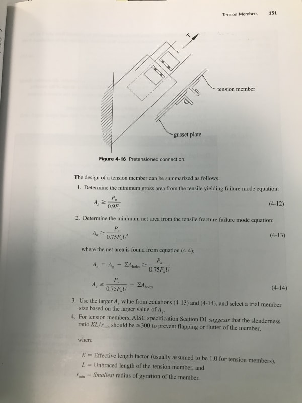
Now for tension-only members, there is a good example in the Seismic Design Manual which actually uses the unbraced length of 0.43L mentioned above for calculating slenderness. And interestingly, they not only give a maximum slenderness of 300, but also a minimum slenderness of 200. This makes some logical sense, as they’re trying to ensure that the compression brace buckles elastically before transferring the full load to the tension braces. Otherwise, i guess the compression braces could be buckling inelastically at low levels of loading. I’d be interested in whether this has been observed in real structures, because I doubt most of the tension-only single-angle systems out there would meet that minimum slenderness requirement. I just designed one that did, and I’m a little concerned about sag now. Maybe I should use rod bracing going forward.

