Eng-Tips is the largest engineering community on the Internet

Intelligent Work Forums for Engineering Professionals

  • Congratulations waross on being selected by the Tek-Tips community for having the most helpful posts in the forums last week. Way to Go!

Grain Bin Inverted "T" Foundation Design Methodology 1

Status
Not open for further replies.

waytsh

Structural
Jun 10, 2004
371
0
16
US
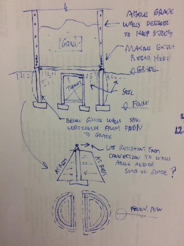
I am working on the foundation design for a large grain bin (90' dia. x 120' tall). Due to the high loads and the fact that there is a tunnel running through the center of the tank I am going to use an inverted "T" foundation. This will allow me to get the footing down to bedrock where I will have a much higher bearing capacity (6 tsf), and with the taller foundation stem wall (7'-6"), I can pass the access hole for the tunnel entirely through the stem wall without interrupting the ring footing.

I am curious about what is common design practice when it comes to handling the outward thrust on the stem wall from the grain surcharge. From what I see I can handle it two ways, either design the inverted "T" foundation as a retaining wall, or size hoop steel in the stem wall to carry all the hoop tension. Perhaps a combination of the two (belt and suspenders)? I realize the hoop steel would have to pass through the headers over the tunnel on either side of the tank in order to remain continuous, bar laps would have to be staggered, etc. Any references that specifically address this design would be welcome too. Also, if there are any other design nuances I should be aware of feel free to chime in. Thank you in advance!
 
Replies continue below

Recommended for you

Thanks JStephen. Hoop steel is what I have used in the past for circular water tank foundations as well. Unless I am missing something I don't see a reason I can't use that here. Assuming I can carry it around the tunnel openings.

Since these loads are so high I wasn't sure if I should consider some overturning effect on the footing as the hoop steel elongates. These loads are much higher than what I have dealt with in the past. Thanks again.
 
I see it like this. Below grade walls spanning vertically to the extent that there is unbalanced load.

image_gavf4c.jpg


I like to debate structural engineering theory -- a lot. If I challenge you on something, know that I'm doing so because I respect your opinion enough to either change it or adopt it.
 
Good idea KootK, a sketch is warranted. Hopefully this helps clear things up (see attached). I should have mentioned that the foundation is supporting a steel bin and the slab is going to be isolated from the stem wall. So the only mechanisms to resist the outward thrust would be hoop steel, base friction, and passive pressure. I was planning to see how the soil forces balance out and then size the hoop steel accordingly. Also note that the tunnel openings pass through the stem wall and do not interrupt the ring footing. There will also be a portion of the ring wall remaining above to act as a header and also allow for hoop steel to remain continuous.

 
 http://files.engineering.com/getfile.aspx?folder=5fc0da24-8cf6-4f0d-b2e7-426d8ef18824&file=CCF05262016.pdf
Got it. The hoop steel makes sense to me so long as you can get the job done in the height of continuous foundation wall available. With the hoop steel in place, I essentially see the wall as spanning vertically from the foundation up to the hoop steel. There will, of course, be some degree of non-hydro-static load that may need a load path beyond that provided by the hoop alone.

OP said:
Since these loads are so high I wasn't sure if I should consider some overturning effect on the footing as the hoop steel elongates.

One strategy that could be used to mitigate this concern would be to use post-tensioned cables for your hoop steel. I fully acknowledge that not every project can afford to pony up for fancy technology like that however.

I like to debate structural engineering theory -- a lot. If I challenge you on something, know that I'm doing so because I respect your opinion enough to either change it or adopt it.
 
Hopefully there is all that high bearing capacity available throughout. In any case, I'd make sure the stem is given plenty of steel so that beam action is generous. The main risk as I see things here is having differential settlement and the lower plates of the bin stretch and pop some bolts, resulting in zipper effect. When that happens all the hoop and other considerations in the foundation are meaningless.
 
Hopefully. Test pits dug so far look promising and are showing that we will be hitting bedrock over the entire footprint. We'll see what surprises await us during the final excavation.
 
Back when I worked for a grain tank company we provided foundation designs as part of the construction manuals (GSI). The tunnel opening through wall was usually spanned using embedded W or S beam in the concrete. The stem walls were just normal walls with vert and horizontal (hoop) reinf but the footings were huge spread out for both uplift/overturning and downward. With grain, is assumed that a large % if not all load (depnding on diameter of the tank) would bridge and make supporting the full weight of tank on the stemwall to footings. The center slab was then overdesigned as a cap slab-on-grade on the center fill. The Tunnel was reinforced for grain loading.
With your situation at 90' diameter the bridging is not as significant and you do need the outward retention from the stemwall horizontal steel or . At 90' diameter x7.5' high, you will likely not develop full tension from hoop steel all the way around and you will likely model it more like a shear wall. I would design the slab as the top restraint with footing as base restraint and have the vertical steel do the job. Then your slab is more like a metal building/hairpin type design. I would not isolate the slab from stemwall. Also your tunnel sidewalls need to have the same lateral pressure applied.

Meadows-concept05282016_0001_anfrg3.jpg


______________
MAP
 
Thank you all for the posts. You need to teach me how to embed my pictures right in the post. Coincidentally this is for a GSI bin; however, the bin size is just outside of the parameters specified in the construction manual.

focuseng, I had considered using the slab as a tie, but both the reaction sheet from GSI and the Geotechnical report are recommending isolating the slab from the stem wall. I think GSI is recommending this because of interruptions in the slab that will not make it continuous from side to side and I think the geotech is recommending this because the stem wall footing will be sitting on bedrock and the slab will be on structural fill. You are correct about the embedded beam over the tunnel opening as well.

They are providing two surcharge loading values; "Floor Grain Load" (3,692 psf) at the exterior walls, and "Non-Dynamic Floor Load" (5,420 psf) at the center of the bin. In the process of developing your manual it sounds like you sized the footings for overturning yet still sized hoop steel. I'm assuming you did not consider the wall "propped" by the slab. How did you determine the amount of hoop steel required? In my situation if I were to size the hoop steel to carry all the load I would need to resist a hoop force of 1.6 x 3.692 ksf x 7.5' x 45' = 1,993 kips. This would mean I would need 1,993/0.9/60ksi = 36.92 sq. in. of steel in the stem wall. This is why I was only going to size the hoop steel for whatever forces are left after accounting for the passive strength of the soil and base friction. Does this seem reasonable?
 
Just a thought...Can you count on developing passive pressure since the hoop rebar in header beam will,hopefully, be resisting large deflection of the top of the 'retaining wall'?
 
Usually the stemwalls were not tall like in your case. For the most part I don't think we considered soil lateral all that much. It was a very basic design:
1) Assume poor soil at about 2-3 ksi bearing, maybe we had multiple tables for a few soil types.
2) The footing was based on full bearing and bending. Just a big donut! Some of those big tanks were pretty awesome in the amount of concrete.
3) Stemwall was also just simple. mostly temp and shrinkage rebar


Frost typically did not extend much past a 4' difference between t/footing and t/slab. The footings were thick so it was easy to get a short wall fairly deep. I remember permafrost were the easy projects -just a big mat:). I worked there back in 1999. I do think you will have a lot of trouble developing and maintaining the tension around the tunnel penetration. 98% of your bars will be terminated and you won't be able to bundle enough through the header at the tunnel if you have a big steel beam in the way. The header at the tunnel was not real deep- That is why we used the steel beams there - Just not enough depth.
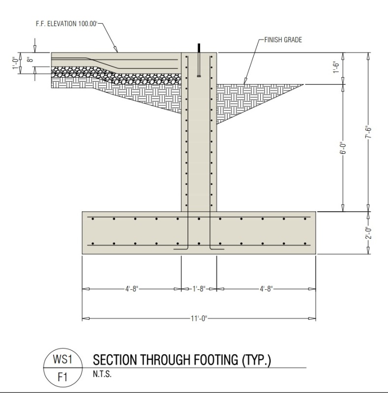
How wide is the footing? Can you make a buttress/wing walls at even increments to use the footing size to your advantage? Can you use the tunnel walls to act as tie beams? Just trying to think of ideas. I think you could make your footing restrained nicely with grade beams. Can you post your footing layout so far?


______________
MAP
 
Here is the footing size I am starting with based off the recommendations in GSI's document PNEG-2073. From the numbers I am seeing so far it looks like I am going to need to increase the thickness of the footing as I am exceeding the shear strength on the toe and heel. I look to be OK for bearing pressure and stem dimensions, even assuming no contribution from the hoop steel.

Ring_Footing_egl8a3.jpg
 
I think the hoop steel is a limited bargain but maybe think of this way:

The radius on the stemwall is 45' so in a way you can think of this as a continuous retaining wall with never ending wingwall (until you get to the tunnel opening) or angled out abutments -design as shearwalls to hold the tension. The footing can be offset or shifted either way to aid in this and you will have plenty of weight and rebar to do the job. At some point the curvature has to work for you right?. Also- you will make a continuous footing/slab to make the bottom of the tunnel which can be used as a tie beam. Since the tunnel opening is an obvious problem, use the sidewalls of the tunnel as tieback shearwalls/counterfort at that location. If you have to put in some wing walls it will be a drop in the bucket -less backfill right[wink].

Maybe a bit unusual to model all this but use the geometry and natural weight of the footings and walls. After all you only are putting in 680 cy of concrete for the footing alone (how many trucks is that??[ponder]). The surcharge is pushing down on the heel too don't forget. Does the tunnel go all the way through or just to the center? I keep imagining it goes through.

Gosh I really just want to tie the slab to it! It is just so CLEAR[curse]

One more odd question, will there be a dryer floor installed? Don't know that it matters much but if you have this floor space maybe there is opportunity there too.
Also apologies for the excessive smileys. it is late and I am trying to avoid real work on a Saturday night.


______________
MAP
 
Haha! No worries about the smiley's, I'm appreciative for the time you are taking to discuss and can overlook a few emoji [thumbsup2]. Perhaps I am up too late as well. I do hate to keep you from your work though.

To answer your questions, yes the tunnel does run all the way through the so there will be two penetrations in the stem wall. Like you said, the tunnel walls and slab would make a good tension tie at least along one axis. I believe there is a dryer floor. I'm not familiar enough with them to know what you have in mind.

Maybe a little off the wall (no pun intended) but I had also considered using the PCA "Circular Concrete Tanks Without Prestressing" to model the stem walls. Once again the tunnel kind of throws a wrench in the approach.
 
Status
Not open for further replies.
Back
Top