Eng-Tips is the largest engineering community on the Internet

Intelligent Work Forums for Engineering Professionals

Gravity columns design in high seismic region 2

Status
Not open for further replies.

compe_ad

Civil/Environmental
Apr 20, 2022
71
0
6
US
Hi all! Can you please help me understand the section 18.14 of ACI (Members not designated as part of the seismic-force-resisting system)?
Section 18.14.2.1 tells you to apply gravity load and design displacement. For the gravity columns, in computer model we will have pinned at the ends. This means we would not have moment developed when structure is pushed to design displacement. But this will increase the shear on columns, right? So wherever in this section 18.14 if moment is mentioned, it applies only to beam right but not for column? Is this the right way of looking at it?
 
Replies continue below

Recommended for you

Unless you have special detailing, the column is more fixed into the surrounding concrete system than pinned.

You could check the moment by assuming the ends are constrained rollers and determining the moment due to the design displacement. The shear can also be determined this way.

 
Hypothetically, if you have a shear wall system that's designed to take the full seismic loads, the columns would be gravity columns and all fall under the "not part of the SFRS", wouldn't they?

Post the code language (in line, please), use the "image" option in your post to attach a jpeg of the code. Also, which code year of ACI 318?
 
I don't work in the US so have no knowledge of ACI etc
However, I'm in a high seismicity country so we deal with similar situations

As DriftLimiter said, without special detailing you will still have fixed connections at the end of typical concrete columns
The usual situation is a shearwall building with concrete floor diaphragm and internal concrete beams/columns to support the floor
The relative stiffess of wall vs slender column/beam means that the drift of the building is completely governed by the walls
This will probably be on the order of 2-20mm for typical low rise buildings
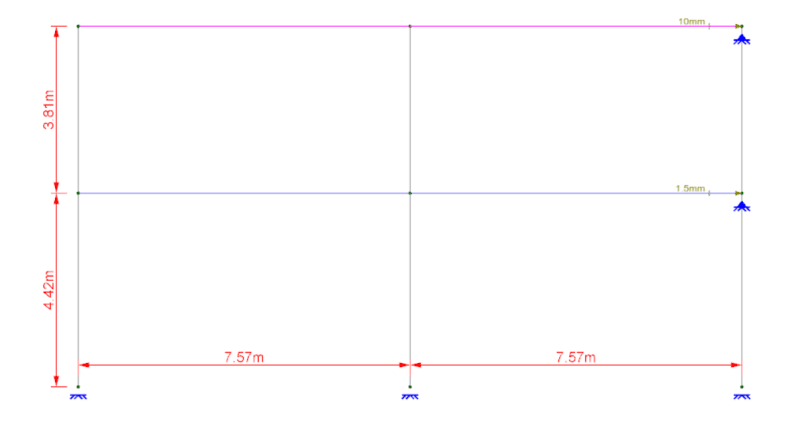
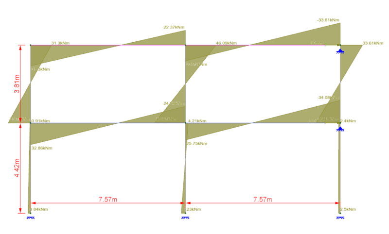
So you just make a model of your concrete frame and apply that drift as a nodal displacement

I would assume a fixed base in this assessment (or at least a realistic rotational fixity) as this will increase the demands for a given drift
Here's a snip from a job where I did exactly that

Drift_bb6p35.png

Moment_wddukq.png
 
@green - do you consider a displacement increased by the q (or R) factor? I get high demand on columns that way, although I use the same method as you. Also, if you place supports, won’t they have lateral reaction from displacements? Is this something that should be considered in design in some
way?
I saw a procedure in a book by Fardis and I could not understand him… he proposed using two models, but not like this I believe.
 

My interpretation a little bit different .
Gravity column design in high seismic regions ( which are not designated as part of the lateral-force-resisting system in regions of high seismic risk) shall be;

– Designed for the gravity load effects and the P- Δ effects .The element must be able to support gravity loads while subjected to the design displacement,
– Provide necessary transverse reinforcement depending on the forces induced by drift. That is , provide necessary ductility.

Pls also look ASCE 7-16 12.12.5 Deformation Compatibility for Seismic Design Categories D through F, C12.12.5 Deformation Compatibility for Seismic Design Categories D through F and C16.4.2.3 Elements of the Gravity Force-Resisting System.

...

He is like a man building a house, who dug deep and laid the foundation on the rock. And when the flood arose, the stream beat vehemently against that house, and could not shake it, for it was founded on the rock..

Luke 6:48

 
My interpretation is closer to Hturkak's.

That being said, my background is more with steel structures. Where gravity only columns are often not part of the lateral resisting system at all. And, many not even be included in the structural model!

These columns must still be capable of experiencing the deflection that occurs during seismic events without collapsing. So, that can affect seated connections or such a gravity beam can "slide" off of it's support. Or, maybe the move induces more eccentric loading / moments in the column due to pure gravity (or unbalanced gravity) loads.

But, most importantly when the gravity columns support a large amount of the total vertical load, these columns need to be treated as "leaning" columns for the lateral system. Meaning the P-Delta effect of these loads essentially PUSHES (through the diaphragm, drags, or collectors) on the lateral force resisting system. If you don't account for this, then you're missing a lot of the geometric non-linearity of the structure.

 
Thank you all for useful information. I haven't understood the behavior of gravity columns during seismic event. What kind of gravity column behavior we expect during seismic event? Of course they won't be designed for high forces that will be induced during the seismic event. Gravity columns will fail which is same case when induced moments and shears exceeds design displacement as mentioned in section 18.14.3.3 of ACI. Isn't failing gravity columns is a problem? I know these are basic questions but can you please help me understand this?
 
To do this properly you would likely need to prepare two building models.

1st model is your primary lateral system model run your various Seismic load cases and then find someway to get the nodal displacements at each column top/bottom and mesh point on the shear wall.

2nd model is your gravity system model column joints should not be released and you need to ensure that your shear wall mesh is consistent with the 1st model or that you have nodes on the wall panel in the same location. In this model create Seismic "load" cases and enforce all of the nodal displacements saved from the 1st model. Then create your combinations as usual and make sure your running a p-delta analysis, if possible subdivide the columns along there length to avoid having to do the moment magnification procedure for p-little delta.

To my knowledge there is not a single software source that can do this procedure in a single model, would love to be proven wrong on this.

I believe one of the primary reasons for performing this analysis is to make sure the lateral displacement does not generate a series of punching failures at the columns, I recall this being a consistent documented failure during Northridge.

I don't believe a 2D equivalent frame model is appropriate for this either unless you have no torsion generated by your primary lateral system, the displacements are only in the x,y direction and not combinations of both.
 
@JoshPlumSE I agree that it makes sense that leaning column will add forces to the LFRS, but using that logic couldn’t the column itself be designed disregarding this, i.e. column is loaded by axial load with a minimum bending moment.

@Celt I’m not sure I understand the two models. The second model is the same as the first one, just that every element can take bending moment? And then you add artificial load to ensure the same displacement as the fist system? I don’t understand this.
This is a different method to the idea that LFRS takes all the lateral force.
 
In order to calculate the induced moments and shears due to design displacement, you can create a load combination that amplifies the moment by "Cd" factor. The inelastic (design) displacement is the seismic displacement amplified by Cd factor. I don't believe you need two separate models, unless you are explicitly making sure your shear walls are designed for 100% of the lateral loads (i.e., pinned columns).

This document is a good resource.
 
Status
Not open for further replies.
Back
Top