abc_poster
Electrical
- Aug 22, 2020
- 2
Hello fellow engineers,
We have a system with the Grid feeding into a YNd TX and earthed on the secondary side by a grounding TX (zig-zag TX). The system (battery inverter) is connected to the above system through a Dy TX.
There are 2 possible sources that contribute to the ground fault current: Grid & Solar/Battery Inverter
Ground Fault Locations (please see image):
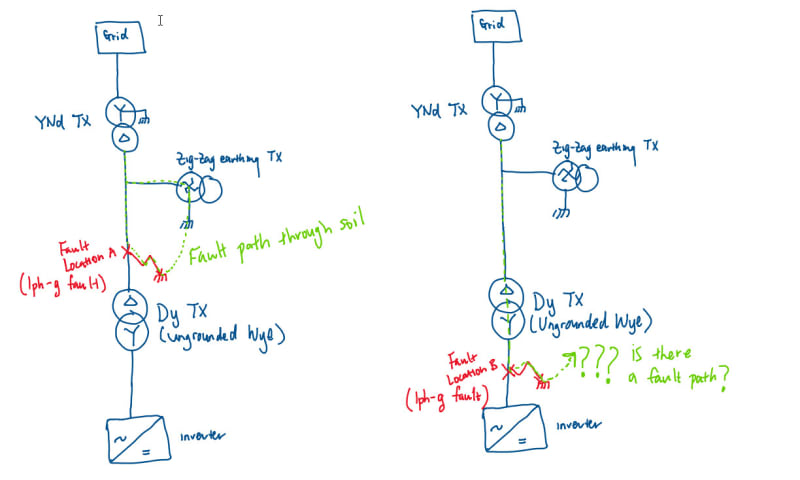
A -
Grid Contribution: I'm almost certain earth fault will flow through the path in green.
Inverter Contribution: Since we have a Dy TX and the ground fault is on the Delta side, there is no return path and therefore is there no fault contribution from the inverter? (if the inverter neutral is grounded does this still hold true?)
Another question is if we did not have the grounding transformer, is there any earth fault contribution from the grid? (since the fault is on the delta side so I think not?)
B -
Grid Contribution: If a fault occurs at B, is there a ground fault current return path? (since the Wye side is ungrounded I think not?)
Inverter Contribution: If the neutral of the inverter is grounded, there will be fault contribution from the inverter.
We have a system with the Grid feeding into a YNd TX and earthed on the secondary side by a grounding TX (zig-zag TX). The system (battery inverter) is connected to the above system through a Dy TX.
There are 2 possible sources that contribute to the ground fault current: Grid & Solar/Battery Inverter
Ground Fault Locations (please see image):
A -
Grid Contribution: I'm almost certain earth fault will flow through the path in green.
Inverter Contribution: Since we have a Dy TX and the ground fault is on the Delta side, there is no return path and therefore is there no fault contribution from the inverter? (if the inverter neutral is grounded does this still hold true?)
Another question is if we did not have the grounding transformer, is there any earth fault contribution from the grid? (since the fault is on the delta side so I think not?)
B -
Grid Contribution: If a fault occurs at B, is there a ground fault current return path? (since the Wye side is ungrounded I think not?)
Inverter Contribution: If the neutral of the inverter is grounded, there will be fault contribution from the inverter.