Navigation
Install the app
How to install the app on iOS
Follow along with the video below to see how to install our site as a web app on your home screen.
Note: This feature may not be available in some browsers.
More options
Style variation
-
Congratulations MintJulep on being selected by the Eng-Tips community for having the most helpful posts in the forums last week. Way to Go!
You are using an out of date browser. It may not display this or other websites correctly.
You should upgrade or use an alternative browser.
You should upgrade or use an alternative browser.
Grounding 3 phase 3 wire system 1
- Thread starter Mbrooke
- Start date
- Status
- Not open for further replies.
RRaghunath
Electrical
I think the distribution is 3-ph, 3-wire. Neutral is not taken to the loads and probably there are no single phase loads directly connected to the switchboard. The Protective Conductor (PE) wire is taken from the switchboard with each of the outgoing feeders. In addition the PE also is earthed at individual installations to lower the earth loop impedance for single line to ground (SLG) faults.
PE as well as neutral of transformer/generator are earthed at the switchboard.
Multiple earthing of neutral (independently at the transformer and at the generator) will split the earth fault current, making it difficult to detect the fault by the protection that is energised by the CT in the neutral-to-earth connection.
Withe existing arrangement, the earth fault current magnitude is seen in the outgoing feeder and the one in the neutral CT will be same.
- Thread starter
- #3
-
1
- #4
Circulating currents through the earth are possible with multiple earthing points. This is avoided with a single earthing point. Also, SLG fault current can exceed bolted fault current when both transformer and generator are earthed, possibly destroying a generator not built to withstand more than bolted fault current.
xnuke
"Live and act within the limit of your knowledge and keep expanding it to the limit of your life." Ayn Rand, Atlas Shrugged.
Please see FAQ731-376 for tips on how to make the best use of Eng-Tips.
xnuke
"Live and act within the limit of your knowledge and keep expanding it to the limit of your life." Ayn Rand, Atlas Shrugged.
Please see FAQ731-376 for tips on how to make the best use of Eng-Tips.
- Thread starter
- #5
davidbeach
Electrical
Where is the protection sensing (LV Breakers or CTs)? The multiple grounds provide paths for current through ground that should be on a conductor and should be sensed by the protection system.
- Moderator
- #7
There are two methods of system grounding for standby generators.
1. the system is designed to be grounded as a complete, code compliant, system without a standby generator.
Then a three pole Automatic Transfer Switch is added and the generator is connected with a solid, unswitched, neutral and no additional grounds.
2. A four pole transfer switch is used and the neutral is switched.
The system is designed as a code compliant system with the system ground point ahead of the ATS. The generator is not considered.
The system is designed as a code compliant system with the system ground point at the neutral of the generator. The utility source is not considered.
Which to chose:
My preference is a three pole switch and a solid neutral. This is cheaper and simpler.
When a protection scheme includes Ground Fault Current monitoring, all of the normal neutral current must return on the neutral conductor. Any shared neutral current returning on thewill be interpreted as a ground fault current and cause a trip.
Another possible issue is the effect of current passing from one grounding electrode to another grounding electrode.
There have been cases where a current passing through the ground has dried out the soil and caused the resistance to ground to rise above acceptable limits.
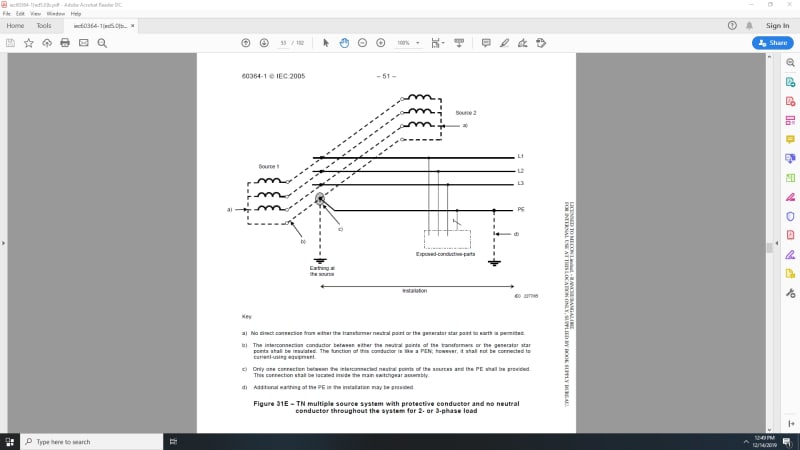
Your diagram does not have headings.
It is unclear as to what exactly to what this diagram pertains to.
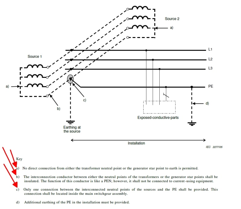
Basically, the customer's installation may have only one connection to ground.
Bill
--------------------
"Why not the best?"
Jimmy Carter
- Thread starter
- #8
Thanks for the replies everyone.
To clarify the diagram is from IEC-60364-1. It mandates that a 3 phase 3 wire system only be grounded at one point which makes no sense to me.
Anyone know their reasoning? I am beyond words mystified.

To clarify the diagram is from IEC-60364-1. It mandates that a 3 phase 3 wire system only be grounded at one point which makes no sense to me.
Anyone know their reasoning? I am beyond words mystified.

- Moderator
- #9
In addition there are often different wiring methods for a neutral conductor versus a grounding conductor.waross 14 Dec 19 17:02 said:When a protection scheme includes Ground Fault Current monitoring, all of the normal neutral current must return on the neutral conductor. Any shared neutral current returning on the grounding system will be interpreted as a ground fault current and cause a trip.
Another possible issue is the effect of current passing from one grounding electrode to another grounding electrode.
There have been cases where a current passing through the ground has dried out the soil and caused the resistance to ground to rise above acceptable limits.
A parallel path for the neutral current may mask a broken neutral or a failing neutral connection.
Most important:- It's the code.
Bill
--------------------
"Why not the best?"
Jimmy Carter
- Thread starter
- #10
- Thread starter
- #11
- Moderator
- #12
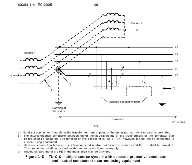
When I look at those diagrams I see a four wire system, not a three wire system.
Even if the neutral is not in use, it is a four wire system.
The neutral must be run from the source to the main switch-gear and grounded in the main switch-gear.
If you don't want to use the neutral you don't have to carry it beyond the main switch-gear.
It may then be considered a three wire system but it is derived from a four wire system and grounded as such.
Bill
--------------------
"Why not the best?"
Jimmy Carter
- Thread starter
- #13
IEC60364 certainly wants it that way- but I'm stumped as to why. It may be four wire, but the neutral is only for grounding providing an effective low impedance path to facilitate the operation of OCPDs. Grounding it at both sources as well as the gear would not present any ill effect IMO.
Compositepro
Chemical
There seems to be confusion on whether the 4th wire is a neutral or a protective earth. In the OP Mbrooke calls the wire in the drawing a neutral but it is labelled PE.
FreddyNurk
Electrical
Some of the confusion may result from the omission of the specific earthing type in the originally posted diagram.
I.e. TN-C is a combined PE-N, where the star point is both earthed at a single point and used as the Neutral, as per the first two diagrams.
The last diagram shows a TN-C-S, where PE and N are (C)ombined ahead of the single grounding point, and (S)eparate when provided to the loads.
The systems shown are all 4 wire. Both arrangements are quite common in LV Remote Power Stations here in Australia, although the TN-C-S is likely more prevalent as separate site light & power is not fed off its own transformer.
EDMS Australia
- Thread starter
- #16
- Status
- Not open for further replies.
Similar threads
- Locked
- Question
- Replies
- 7
- Views
- 5K
- Question
- Replies
- 4
- Views
- 7K
- Locked
- Question
- Replies
- 7
- Views
- 7K
- Question
- Replies
- 6
- Views
- 6K
- Locked
- Question
- Replies
- 11
- Views
- 3K


