Eng-Tips is the largest engineering community on the Internet

Intelligent Work Forums for Engineering Professionals

  • Congratulations waross on being selected by the Eng-Tips community for having the most helpful posts in the forums last week. Way to Go!

GSD STUDY 2

Status
Not open for further replies.

CAD2015

Computer
Jan 21, 2006
1,932
US
Hi,

How could I convert all the surfaces included in the Geometrical Set.1 into a solid?
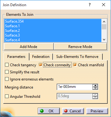
I run "Join" in GSD:
image_ndkisb.png


image_t5s19g.png


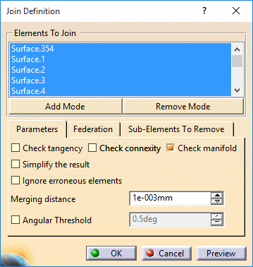
Then unchecking the "Check Connexity box:


image_reiznw.png


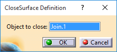
and then "Close Surface" in Part Design:

image_g8vktr.png


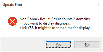
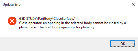
But I got this message:
image_tojy2g.png


Can you help me to find the right method to get a solid body?

Thanks!


CAD 2015
 
Replies continue below

Recommended for you

1 delete the join you did
2 create new join with default parameters Check Connexity and Check Manifold = true
3 select last surface from your geoset
4 from the Create Join GUI, select your surface and rightclick Distance propagation
this will help avoiding none connexe element​
5 do a preview see the holes in green (1 big and few small)
6 change merging parameter to 0.01mm
7 do preview again and see that small holes are "gone"
8 smile you are progressing and validate the join
9 select all surface in no show (all but first one and join)
10 create a geometrical set (by default all selected element will go inside the new geoset), this will make shorter tree to work with when you shrink the new geoset
11 define old geoset as current
12 create boundary curve of join
13 project the boundary on the first surface (354)
14 disassemble the projection
15 delete the few lines/curve in the corner
16 extrapolate the line too short up to the other line, working on surface.354 as support
17 create a new join
18 select the extrapolate
19 in the GUI, do the rightclick distance propagation again
20 do preview to make sure the curve is closed
21 split surface.354 with join curve, keep the inside :)
22 create new join with first join and last one
23 do the preview / merging distance again
24 extract boundary of last hole
25 fill the boundary
26 make last join with fill and previous one
27 adjust merging distance with preview
28 make solid from last closed surface
29 go get a drink, you deserve it (I know I do...)


Eric N.
indocti discant et ament meminisse periti
 
Itsmyjob,

Thanks a lot for your fast reply.
Can you add the CATPart that I suppose you've done?
I'd like to analyze it and learn your procedure on a logical succession.
Thanks!

P.S. I use Catia Version 5-6 Release 2016


CAD 2015
 
sorry 3DX18X, export will not help you as all will be isolated.
just follow the steps it should work
if not, post your progress and i will look at it

Eric N.
indocti discant et ament meminisse periti
 
Itsmyjob,
I got up to here:

1 I deleted the join I did
2 I created a new join with default parameters Check Connexity and Check Manifold checked
3 I selected last surface from the Geometrical Set.1 (Surface 353)

From this point, I wasn't able to advance:

4 "[highlight #FCE94F]From the Create Join GUI, select your surface and right-click Distance propagation this will help avoiding none connexe element[/highlight]"

Q What did you mean by "Create Join GUI"? What "GUI" stands for? Sorry, I am not a proficient GSD terms user......


CAD 2015
 
if you set merging parameter to 0.1 you will get rid of all the small holes... you will only need to trim the first surface (.354) with the boundary of that join.
then add the two surfs (Join and Trim) into a new join (having same 0.1 merging tolerance).
and make solid by the closed surface command

regards,
LWolf
 
Thanks LWolf,

I'll try that right now.

CAD 2015
 
LWolf,

It works, I got the solid!
It looks like the surface 354 was larger than the area where it should have fit and creating another surface( I did that, instead of trimming surface 354) fixed this
issue.
Was this the only issue that caused the initial failure?


CAD 2015
 
GUI mean Graphic User Interface its the windows that opens when you start the Join function.
in that window you will find the surface you select (in 3D), then you right click on the text inside the GUI to get propagation mode.


Eric N.
indocti discant et ament meminisse periti
 
Itsmyjob
LWolf

How did you find out about that unfit surface (354)?
Checking each of all 354 surfaces take a lot of time!

CAD 2015
 
i picked a random surface and did the join propagation, the only one left was surface.354

Eric N.
indocti discant et ament meminisse periti
 
itsmyjob
LWolf:


Please, read the summary below and let me know if I got to the right conclusions.
In order to get a solid from the given surfaces I have to:


1. Create another surface that would replace the unfit (larger) surface 354 (Used Fill)
2. Create a Join from all connected surfaces (1 to 353+Fill.1)
3. Create a solid (CloseSurface.1)

What do you think?

CAD 2015
 
yes that's it, including the usage of the merging distance that will make some holes "disappear"

Eric N.
indocti discant et ament meminisse periti
 
Yes, I got that detail, too.
By the way: What does merging distance do, that will make some holes "disappear"? How the different values of it makes the difference?

Thanks a lot!

CAD 2015
 
By following Eric's 29 steps you will learn the proper way of working! Pls. spend some time analyzing each step--projecting, disassemblying, boundary, join...
all crucial steps in surface fixing. press F1 for each function to jump right into CATIA help--that way you should be able to learn about each function...
good luck!


regards,
LWolf
 
I hope some will do all 28 steps before simply doing #29

Eric N.
indocti discant et ament meminisse periti
 
cad2015 said:
What does merging distance do, that will make some holes "disappear"? How the different values of it makes the difference?

merging distance parameter will just tell catia to ignore gap bellow the value. It will not actually modify the surface, just tell catia not to look at small (under value) gap.

This solution might have an impact downstream, and maybe you wish to fill all holes or modify surface to avoid holes.

to fill holes, well you know what to do (29 steps).
to modify existing surfaces use the Healing command - there are limitations here. (that would usually be my last choice as it is not that easy to fully control what is done here...)

Eric N.
indocti discant et ament meminisse periti
 
Thank you for your time and for funny comments; I did enjoy them!

image_vswcoy.png


CAD 2015
 
Status
Not open for further replies.

Part and Inventory Search

Sponsor

Back
Top