Continue to Site

Eng-Tips is the largest engineering community on the Internet

Intelligent Work Forums for Engineering Professionals

  • Congratulations SSS148 on being selected by the Eng-Tips community for having the most helpful posts in the forums last week. Way to Go!

Guidance Notes wrt King Post Retaing Wall

Status
Not open for further replies.

richard4556

Electrical
Oct 30, 2011
39
In the UK if you wish to put up a retaining wall under 2m high, as long as it is not near a highway or next to building foundations, you can - without planning permission or advising building control. What DIYers do when building a retaining brick wall, is take note of construction guidance, often published by brick manufacturers. The situation may be the same in the US, I'm not sure.

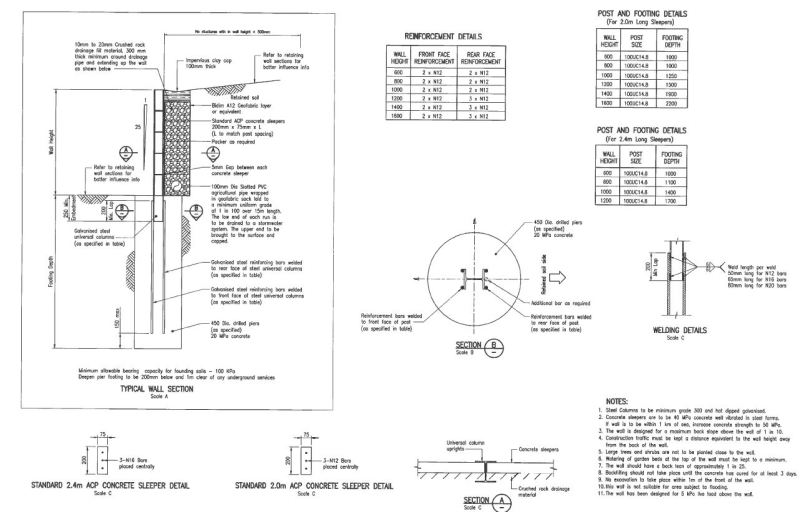
However, if you wish to erect a king post wall and use railway sleepers (ties) there is not (it seems) any equivalent guidance.

Is there any structural / civil engineer on this forum able to write a guidance note for erecting a king post retaining wall made with "I" beams and railway sleepers? For a height say not exceeding 1.5m Possibly a public service project. :) Thanks.

EDIT: Might suit a civil engineer who has a website. Guidance could be published on your website. Could you produce guidance notes for a worse-case scenario for a 1.2m retaining king post wall with railway sleepers as infill panels, posts made of steel "I" beams, where the banking that is being held up is soil and level?
 
Replies continue below

Recommended for you

This should have been posted in the Earth Retention Engineering forum.

This type of wall is known as a soldier pile wall in the States. Soldier pile walls are more common here as temporary walls instead of permanent. Solider pile walls are also used as sound barriers on sides of highways. Railway sleepers are known as railroad/railway ties in the States and are usually fabricated of timber material, not concrete.

Here is a general design guide.


Some discussion is here:

 
Thanks for the snippit of information.

I wonder if ADMIN could place this thread in the right spot. (Earth Retention Engineering forum.)

 
It would appear the poster (Richard) is not planning on anchor rods back into the zone well back from a failure block as the drawing by WA.gov shows. Individual posts of relatively small "diameter" holding back some form of wall (rr ties) is asking for a lot of soil passive resistance to failure under that lateral loading. Some folks (some railroad maintenance guys mainly) use this a lot and they usually don't hold back much height of backfill, like a few feet mainly. If you really want to do this and make it work, you need soil properties of both the supporting material ad the retained material. My guess is that you will be darn lucky to get it to work, unless the rails are closely spaced, like a foot or so and that they probably have to be at least 2 meters into supporting soil.. A geotech engineer ought to be able to help you. For the heck of it drive in a single rail to where you think it might "work". Attach a cable or chain to the top and pull with a vehicle. Observe whether the rail bends or the whole thing leans. A rough test of both the ground and the rail may guide as to where to go next..
 
Here is one I came across that uses structural steel columns and concrete sleepers:

Capture_mglkeg.jpg
 
Hi. I've uploaded a drawing to make things clearer.

If I want to build a small domestic clay brick retaining wall, in which the design represents the meeting of an obligation to put up a adequate wall, in terms of safety, then I can download a guide note from a brick manufacturer. In the UK, there is no need for planning permission or building control for small walls as long as they are not near highways or building foundations. But, of course a retaining wall needs to be safe.

In the picture I've provided, at the top (A) shows an adequate design for a clay brick retaining wall of 1 meter height. As long as ground and water pressures are minimal, it's a safe wall. It tells me I can put in a concrete foundation 500mm below the surface, 600mm wide and 125mm thick, and it points our other things as well.

Now, I'm not a structural engineer, but I imagine it ought to be possible to create a guidance note for a king post retaining wall (soldier pile and lagging), given certain restraints and conditions. For example the restraint that the wall is no more than say 1.4m in height and that the posts are steel and the lagging boards are no less than 100mm (4 inch) thick (as many railway sleepers are in the UK).

In the picture, (B) shows a king post retaining wall 1.2m high. There ought to be no issue with the steel posts, they will not bend I feel sure. The issues are span "S" and the nature of the foundation for the posts. Notice, the steel posts are either "I" section, or "C" section. In both cases quite substantial.

Link to my drawing below:

So, is it reasonable to create a guidance note for a king post retaining wall, given the restraints and conditions mentioned above? And what would that guidance note look like, in terms of span "S" and the concrete foundation?
 
 http://files.engineering.com/getfile.aspx?folder=7b290b40-1502-4508-a52f-053f2d873d4d&file=Drawing_of_Retaining_Walls.jpg
Richard: A Rule-of-thumb for gravity retaining walls, which each of your And B appear top be, is that the width(front to inside) has to be about 1/3 the height. Your two examples, A and B appear to be roughly that barely. However, they need to be one unit, "glued" together. Just sitting on a slab is not keeping things together. Mortar is not structural glue. If there was some form of reinforcing connecting all parts, maybe. Your "King Posts" barely into the slab is not a valid connection. If all parts are connected suitably, a simple gravity wall analysis will show if it works. The king post wall is not a gravity wall at all. Not heavy enough. With suitable reinforcing, it might be looked at as a centilevered wall, but even then scarcely. .That is where someone familiar with doing those checks comes in.
As I look at the various alternatives, none are likely to work (for sure). Get a geotech involved.
 
Just because the wall is less than 1.4 meters in height does not mean that the wall should not be designed by a competent person. Someone with experience should evaluate the soils behind the wall.

You don't have to search far to find an example of a wall where someone underestimated or misunderstood the forces that soil can exert. Tilted, bulging, or tipped retaining walls can be found just about anywhere there are hills and construction. In some cases, designing a sound retaining wall can become a very complex task that is best left to an engineer. You also need to evaluate the long term maintenance aspects.

Don't understand why you are focused on soldiers piles either. One would think that a soldier pile will be more expensive to construct than a block wall.

 
I am not a structural engineer, but, these are my thoughts: Drawings A and B are not to scale. A shows how to build a small retaining wall given certain assumptions, one of which is the wall is no more than 1m high. It's "designed" or drawn up by a brick manufacturer, in a series of "Get it Right" articles. Clearly the wall is a gravity wall, and I assume that the wall has some capacity to retain simply by virtue of the mass of the wall (which is one brick length in depth -two skins tied together in fact) being sufficient to counter slippage at the base and turning over due to a bending moment. As long as the foundation is 600mm wide and 215mm thick and at a depth of 500mm, the article should be good for a retaining wall. At least, the brick manufacturer is putting it out, (by publishing) - that the design is good - given the assumptions indicated. Thousands will rely on the article, and I do not believe anyone has argued the article is creating retaining walls that are inherently dangerous. Of course, one could do better and place pillars in the basic design.

As to wall B. That is my initial concept of a king pole wall with wooden panels. Yes, it does not look like a gravity wall, and so it needs to be a form of cantilever wall. There is a hint of a cantilever in the lower left drawing, showing the post in concrete. The question would be is can a cantilever be created by placing a steel beam into some form of concrete foundation structure? As to the boards and the posts as drawn - indeed the boards only "connect" at their extremities with the beam members and so not a valid connection. Although you may see this design feature in some retaining wall offerings by some concrete panel manufacturers (if I'm not mistaken).
 
Richard, you seem fixed on a few things but without a background in structures, etc. You are assuming some details that none of us would consider. For instance we would install reinforcing rods in those brick walls and the footing they sit on to take the tensile forces and to tie everything together. You can't depend on any form of "glue" when it comes to connection to c9oncrete. You show no such ties. The idea of connecting a King Post to the foundation takes a lot more than shoving the end in wet concrete. If that were even possible with a fancy group of steel reinforcements, the twist of the footing between posts would have to be addressed. The bending moment on that post is very high. Also in these forums we do not attempt any form of design. Me being also an amateur radio fan, I have some electronics know how, but no way would I try to design even a simple crystal receiving radio these days.

I suggest looking into a crib wall made with those RR sleepers. Here are some ideas of larger walls. Be sure to tilt it back a little for better stability. Rough out the dimensions by a scaled method. I would bet you can do it much cheaper than as indicated with the King posts. Backfill the crib with sand and gravel for drainage.


One more from the Old Guy. Those brick manufacturer's recommendations are on the very edge of being suitable. Without a good tie to the base support, my bet would be yous will tilt over for sure. Tied to the footing it still may fail under some circumstances.. Do a simple gravity check as the quoted link shows. Use the earth pressure as "at rest". Add any surcharge loads also.
 
I have a feeling that if a contractor put in posts for this king post wall, the steel beams would be sunk no less than 2 meters in the ground. And if a cantilever was made a contractor would weld onto the bottom a beam say at least 1 meter normal to the post.
 
OG again. I was thinking of sketching up some details for the "connection" at the bottom of the posts, but with no design. I would guess that no checks have been made yet, but here is what would be required as a minimum of a "check". Develop the pressure diagram against the wall from the earth backfill; find the bending stress in the lower plank for given spacings of the posts; find the post bending stress at the top of concrete for the post. Assume a good connection is made there. Then find the soil toe pressure coming from the "footing". Modify this footing width if necessary to suite soil bearing allowed. Without any of that and using "seat of the pants" that it is "good enuff", who ever cuts the posts to suitable length probably has (or should have) enough shop equipment and smarts to figure out and develop a good bracket at the bottom, such as welding on a section of the channel used at ends, bolted on angle brackets, heavy rods in drilled holes of the post, etc. All of which is estimated as "looks strong enuff". That bracket should have the ability to carry the full bending moment at the bottom of the post. Without doing a "set of the pants guessing", a geotech ought to be able to to the bulk of the check. Exactly what is needed t the post base can be figured out, but concrete strength there and other details may take a little more work.
 
OG with a story about "seat of the pants" building. For many years my brother, not a college graduate, but a pretty good mechanic seemed somewhat jealous of my success as an engineer. He was an old engine enthusiast and wanted to build a goose-neck trailer to haul his heavy engines around the country to week end engine shows. I offered to help size the steel members needed for this big goose-neck trailer. Of course he was too proud to ask for any help. About a year later I was visiting him and noted he had it all done and was rather quiet about showing me the thing. Anyhow, even though I didn't do any calculations, I could see,comparing his to similar capacity commercial built trailers,that his was built at least twice the strength of any I have seen, maybe even more. I think I could have saved him a lot of time and expense, but pride got in the way.

The lack of some simple engineering checks can come back and bite the "seat of the pants" guys, either not enuff beef in it or well over built.
 
OK. I'm now getting more and more convinced that it's not good trying to put up a king post fence as a retaining wall. As an inexpensive concept it isn't apparantly working. I'll probably put up a commercially made segmented retaining wall, or a regular brick wall, based on BRE 27 "Building brickwork or blockwork retaining walls." Rich
 
Rich: Your original request for some form of "design" where blanks can be filled in maybe would be fine for something like say sizing an air conditioner for a given area of house and form of construction in a given climate, or maybe what mix to use for getting a given strength of concrete. However with the numerous possibilities for the post supported wall that is pretty much not something that can be reduced to "filling the blanks", especially with the support by a footing. I thought maybe the low cost or free supply of RR sleepers was the incentive.
 
The thing is, here we are in 2016, and it looks like no-one has bothered to publish to the world a guidance note on erecting a king post retaining wall above say 1m, using RR sleepers. Now, if that is true, that is telling us something. That the material selection is amiss. I did a search of "Retaining walls" and ordinance. Google comes up with some good materials on that search (mostly US). And you will find that some councils specifically prohibit wood in retaining walls. I just think then, that I'm onto a hiding to nothing using wood in retaining walls. And when I did a price calculation, using concrete as infills, it was prohibitive.
 
Rich: Over here sometimes the RR's give away or sell cheaply the ties that are not suitable any more. Not sure of the dimensions but they are roughly 7 inches by 7 inches. Many a landscaping job uses them, but in modified crib methods. They are treated with creosote and that is rather messy stuff. Treated timber also is available, usually lower grade soft woods treated with copper type solution (some very poisonous). For underpinning bracing usually the wood is hardwood, sometimes salvaged after concrete is placed. Good luck.
 
Status
Not open for further replies.

Part and Inventory Search

Sponsor