Eng-Tips is the largest engineering community on the Internet

Intelligent Work Forums for Engineering Professionals

  • Congratulations waross on being selected by the Tek-Tips community for having the most helpful posts in the forums last week. Way to Go!

Gusset Plate Whitmore Section 2

Status
Not open for further replies.

Yochael1996

Civil/Environmental
Jul 21, 2020
21
0
0
US
Hi All,

I am currently evaluating a gusset plate, and the Whitmore section confuses me:
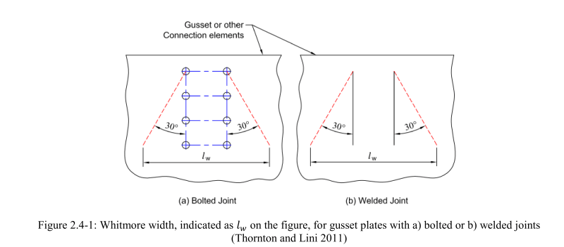
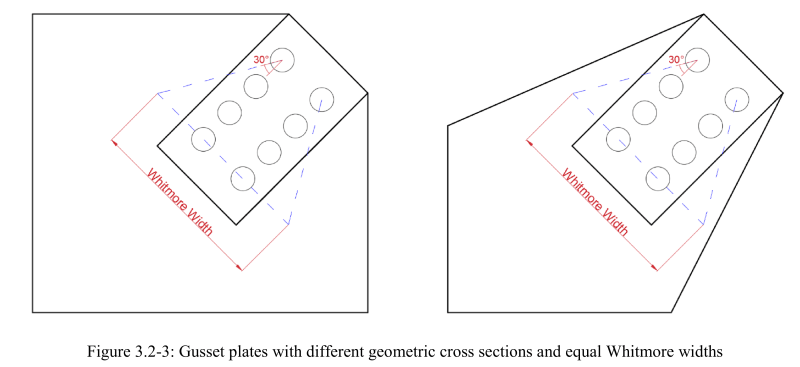
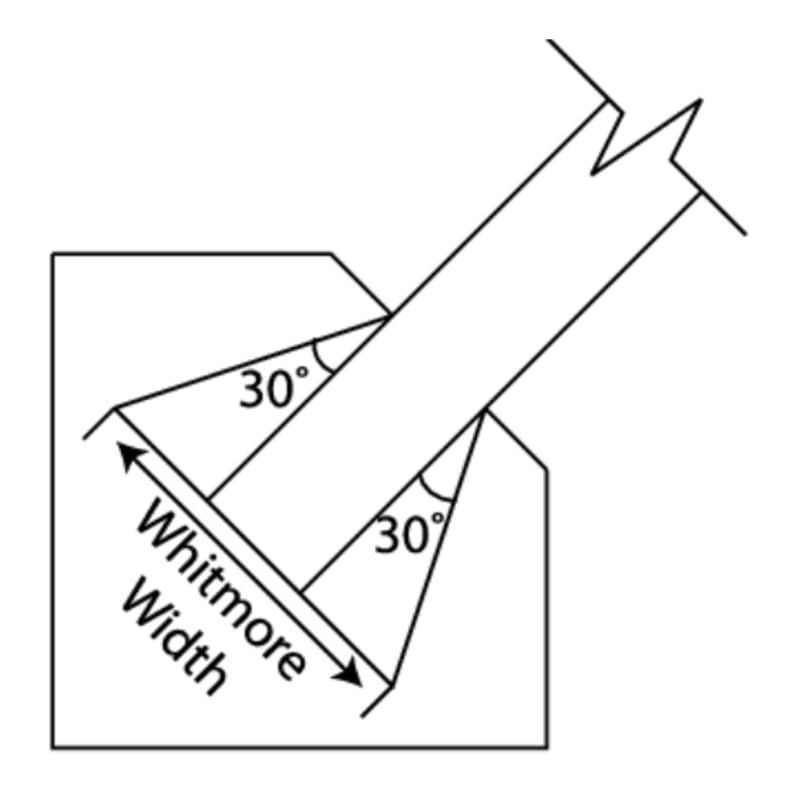
Typically, the Whitmore section can be easily found by the two 30-deg angles, like shown in the figure:
Typical_eszbre.jpg


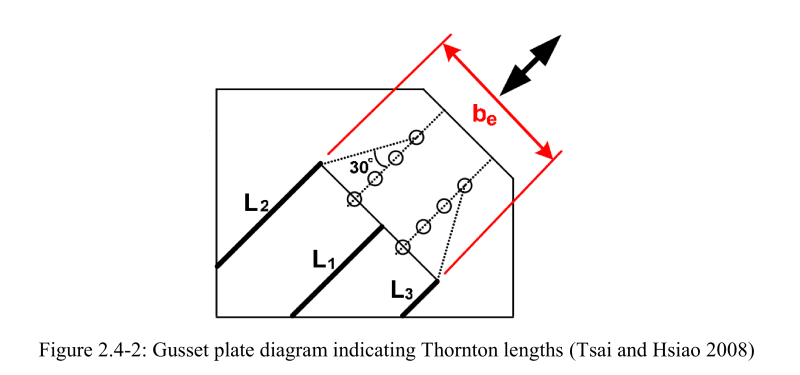
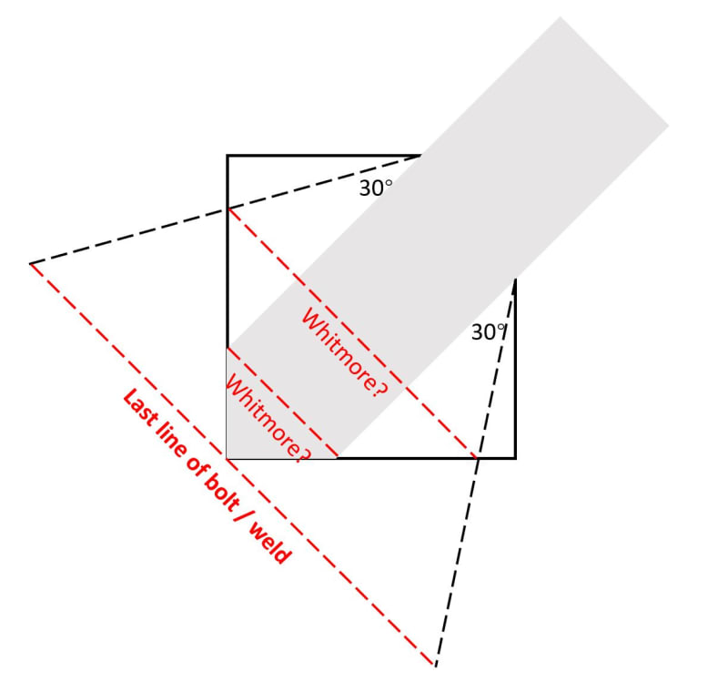
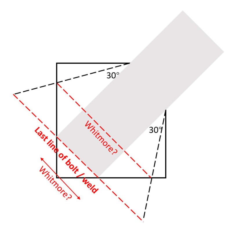
However, I meet a case that the truss member is all the way welded along the gusset plate, and the Whitmore section becomes not clear to me. I tried to draw my confusions in the following figure:
ConfusingCase_kwn6hd.jpg


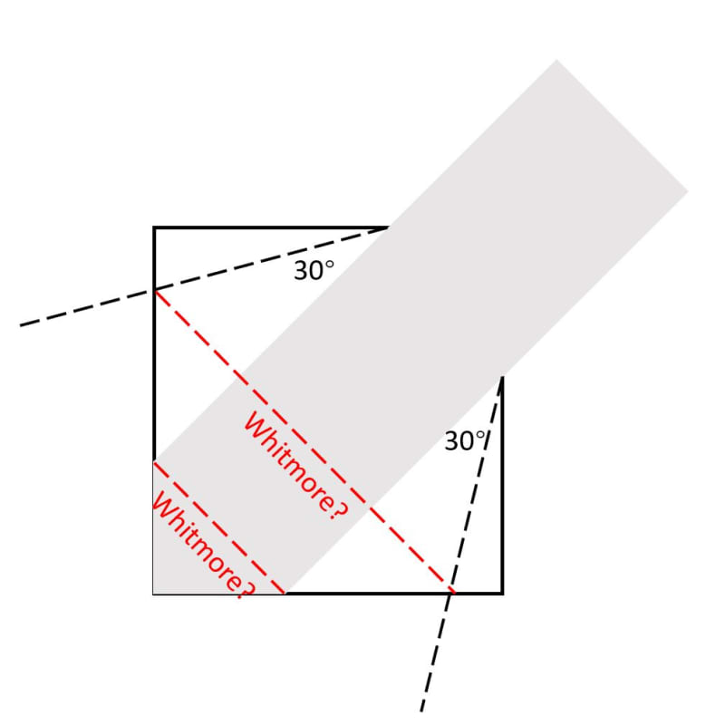
Can someone advise what should be the appropriate Whitmore section for the second figure? Thank you in advance!
Yochael
 
Replies continue below

Recommended for you

It's definitely the longer one to me. But, this is almost irrelevant. I can't imagine this having a gusset buckling issue if the truss member is welded all the way back to the the joint with the other members.
 
Usually the whitmore width is only relevant only to tension cases, and it is the width at the last set of bolts (or weld) with the spread starting at the first set of bolts or weld.
image_aqjboq.png


For compression buckling an effective length concept is usually applied. The average of the three lengths shown below is sometimes used for buckling.
image_j3b5et.png


Have a search on the internet, plenty of advice out there on these concepts.
 
One other important point to make here, even for quite different gusset configurations, the whitmore width and hence tension capacity of the gusset will be the same.

image_htozbb.png
 
Hi Agent,

Thank you for replying!
I was aware that the Whitmore section typically refers to the last line of the bolt/weld, however, in the case that I drew, the Whitmore section intersecting with the last line of the weld is complete out of the connection plate, as shown below. From what I understand, the Whitmore section should be on the connection plate - does it mean that this connection has a Whitmore length of 0? I personally don't believe so but I don't know what should be the proper Whitmore section...Please advise!
WeldWhitmore_yyfbvj.jpg
 
Hi JoshPlumSE,

Thank you for replying!
Yes, I would agree with you that an effective buckling shape cannot be developed for this connection plate.
In this case, I am evaluating the tensile capacity (Whitmore section yielding). It looks to me that the Whitmore yielding is not likely to happen in this case as well, but I am still wondering what would be the proper Whitmore section for such cases where the connection (i.e., riveted, bolted, or welded part) is very long. The reason why I am confused is that the Whitmore section is determined based on the last line of the connector, but when the connectors are very long, the Whitmore section becomes out of the connection plate, potentially resulting in a really small Whitmore length. Two simple examples are shown below. Could you please advise what would be the proper Whitmore section in these cases?
Thank you in advance!
WeldWhitmore_fcdsng.jpg

WeldWhitmore2_cvx8k6.jpg
 
Is that the yield line surface? If so I believe it is always limited up to a certain value: 20*t_gusset for single plate support and 50 * t_gusset for double support.
 
Hi Kostast,

Thank you for replying!
Yes, I am talking about the yield line surface. It is good to know about the upper limit. Could you advise what is the reference for this limit (20 x t / 50 x t)?
Additionally, I am not worry about the upper limit - I am worried about if the Whitmore section is too small when the connection is too long, such as the case shown below. Could you please advise? Thank you!

Sincerely,
Yochael
WeldWhitmore2_c57p6h.jpg
 
The only source I can provide you with is the Steel Construction Institute (SCI) Green Book.

Check the link and download the book. There is a chapter with the background + example. Pages 261, 262 (271 of the PDF)

Link

I remember when I was researching stuff at university came across this in some ASCE publications for Buckling Restrained Brace (BRB) frames for earthquakes. Don't remember the specific papers anymore.
 
A quick search came up with this from New Steel construction. A nice article.

Just to clarify the formulas are for the interaction of axial force and bending.

"A limiting width of 20t is needed, except for gusset plates supported
on two edges, where wguss can be up to 50t. Designers will find these widths
exceed the traditional ‘Whitmore’ width for the majority of conventional
designs."

Link
 
Status
Not open for further replies.
Back
Top