Continue to Site

Eng-Tips is the largest engineering community on the Internet

Intelligent Work Forums for Engineering Professionals

  • Congratulations KootK on being selected by the Eng-Tips community for having the most helpful posts in the forums last week. Way to Go!

Hanging Equipment Support from 1 Column

Status
Not open for further replies.

cgstrucg

Structural
Mar 21, 2018
135
Hello,

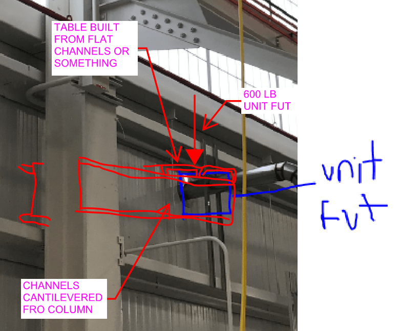
I have a weird situation in which I have a 600 lb mechanical unit to support in the air. The weird part is that I can only use one column to support. Please see attached photo for more clarity. I thought of putting 2 inverted knee braces on column one leg vertically (say y-direction) and another leg horizontally in the x-direction. From the horizontal leg, I thought of putting 2 horizontal unistruts in the z-direction. From there on putting 4 vibration isolation rods into the mechanical unit to support it. Unistruts can be braced and horizontal legs of knee braces can also be braced to stop torsion.

I thought this model to be good but the only issue now is the rotation of the unit and hence the rods. How do I restrict that? Can someone provide some suggestion this?

Also you can suggest alternatives if you have to support the unit in air with the column. it will be really appreciated.

Thanks
PK
 
 https://files.engineering.com/getfile.aspx?folder=4e21a45e-ca3d-44d0-bd1d-0c6164f41631&file=1.PNG
Replies continue below

Recommended for you

600 LBS isn't all that much so you've got some options. I'm afraid that I don't understand your proposal however. It might be prudent to post a sketch.

c01_z6gk7b.png
 
I too need a better sketch of what you are describing. Also, you need to make sure your future unit is somewhat to scale. The size drawn on the picture looks kinda small for a 600 lb mechanical unit.
 
" I hope this CAD will make ...... "

D -

You can take a re-test, but the score will be automatically be lowered two full letter grades.
 
Can they move the equipment "up" some in your drawing to at least align with the column to the right? If not, you have a bi-axial headache one way or the other. Assuming the column is strong enough you could somewhat apply Kootk's drawing 2 times with the column being at the 90 degree corner of a triangle. Provided you cantilever enough, you could connect a platform between these 2 cantilever arms. I am not sure how much vibration goes on but you would be cantilevered at least 7' to 8' based on your drawing.
 
I tried but I don't think the unit will in any way be able to align with the column so can't use Kootk's method.
 
Well we aren't Wizards/Witches, at best we're magicians the way we can fool the eye to see what they want. Some cases however, the trick just can't be done.

I might be on board with something like Koot's proposal. Cantilever something off of the column (preferably a tube section) the long direction such that it puts the column in mostly strong axis bending. Then cantilever a platform off of this tube such that the tube is seeing bending and torsion, and the main column sees bending in both directions.

Without running numbers I don't know if that is truly feasible without major reinforcement, but it's a thought.
 
600 lbs isn't much, can you suspend it from the roof framing? You can install a lateral brace to the column in your photo so it doesn't swing around.
 
Yes, I am also trying to suspend it to roof framing now. Can you tell me how the hangers work in this scenario? I have never seen a suspended hanger system design. The roof beam is level to the beam showed in the initial photo and approx 20 ft up.
 
What is the secondary framing on the roof - light gauge purlins, rolled beams? What is their spacing? You could try to suspend it from the main beam that is inline with column in your photo, but now you're back to dealing with the offset. If you can split the load between two purlins, you're only putting 300 lbs on each, very close to the end of the span. That would be my first choice.

Picture of the roof framing?
 
Right. There are beams at every 8 ft spacing. I can use them perhaps. I think I got it. Maybe a few tweaks. Can you see the attached photo? Anyone has modifications they can suggest. Using my method it is only braced in one direction. It still needs to be braced in another direction.

Made in hurry so not at all to scale
 
 https://files.engineering.com/getfile.aspx?folder=f8dd7d9a-bf1b-4498-992a-e07eee2c710b&file=2.PNG
So this approach is creating more issues and now we are thinking of supporting the unit from the floor slab. The bottom of the unit is at approx 10 ft from the slab. I am thinking of using 4 angles at the perimeter of the unit with 4 posts coming down and ending in a base plate. Does this approach sounds right?
 
I think any of these approaches are a good start. The loads just need to be worked out and designed for.

-MMARLOW EIT
 
OP said:
So this approach is creating more issues and now we are thinking of supporting the unit from the floor slab. The bottom of the unit is at approx 10 ft from the slab. I am thinking of using 4 angles at the perimeter of the unit with 4 posts coming down and ending in a base plate. Does this approach sounds right?

I'm seeing:

1) One generously sized, central HSS column

2) Cap plate with gusset stiffeners below.

3) Lateral tie-back near the top using jayrod12's proposal above.
 
Actually, I am thinking of providing vibration isolators at the end of the post as it's a mechanical unit and a central HSS will transfer all that to the isolator. Using 4 posts, we will be able to divide that DL. Few issues now are tripping hazard at the base of vibration isolators and the connection between angle to angle, and angles and post. Can they weld angles to each other to make a resting place for the equipment and then those angles to the 4 posts at corner?
 
There might be some concerns with welding and vibrations? Look into fatigue loading. You're loads are really low, so it might not be too big of an issue. Im not really understanding your issue with KootK's HSS approach? Why split up the dead load?

-MMARLOW EIT
 
I mean I can use that approach, it' very easy and contractors might like but I am not able to find a vibration isolator which is economical and can take that much load. Also, how will I make the unit not tip? By using braces at all 4 sides of the unit attached from the central HSS?
 
OP said:
but I am not able to find a vibration isolator which is economical and can take that much load

I obviously don't know your exact situation but can you not stuff four isolators between the column cap plate and your thing?

OP said:
Also, how will I make the unit not tip?

As I mentioned in my last post, use Jayrod's solution. Extend some kind of frozen Canadarm thing off of the existing column to laterally stabilize the new post near the top.

Your unit is something like 4' x 4' in plan right? When I visualize that as a 10' tall, 4 leg thing, it just feels a little silly to me. It would require cross bracing and still probably be slender enough that it would be susceptible to lateral vibration issues. Am I missing something? Are you planning to build a larger platform than I'm envisioning?

c01_bch3e8.jpg
 
I wanted to give Jayrod's thing a try but the issue is that when we told that idea to contractors they told us that it would obstruct a crane at the top. So we went for framing from the bottom.

I am not putting vibration isolators at the top but at the bottom. Like the one shown in the image. Platform will be 4'x4'
 
 https://files.engineering.com/getfile.aspx?folder=35937094-15a2-4200-953d-36045cdebefa&file=1.PNG
Status
Not open for further replies.

Part and Inventory Search

Sponsor