I have come accross a spiral bevel gear set, 5DP, used in a milling head drive. The gears run with very little backlash. The material analysis showed that those gears were made of 17CrNiMo6, a 1 mm thick carbourized layer has been also found. The surface hardness of the teeth was measured 68 HRc, while a typical would be around 60 HRc. The measurement has been confirmed by checking in different places. Does anybody know how did they achieve 68 HRc on 17CrNiMo6?
Navigation
Install the app
How to install the app on iOS
Follow along with the video below to see how to install our site as a web app on your home screen.
Note: This feature may not be available in some browsers.
More options
Style variation
-
Congratulations TugboatEng on being selected by the Eng-Tips community for having the most helpful posts in the forums last week. Way to Go!
You are using an out of date browser. It may not display this or other websites correctly.
You should upgrade or use an alternative browser.
You should upgrade or use an alternative browser.
Hard spiral bevel gear set 1
- Thread starter spigor
- Start date
- Status
- Not open for further replies.
gearcutter
Industrial
68 HRc..............hmmmmmm, I doubt it.
Can you describe the measuring device and procedure used to take the hardness readings?
Can you describe the measuring device and procedure used to take the hardness readings?
I would agree with gearcutter. The material described definitely responds well to carburizing, and the .040" case sounds about right for a 5DP tooth. But even the case surface hardness as-carburized would not be Rc 68. And if the gears were finish ground, the case surface hardness would likely be somewhere around Rc 58-62.
Like gearcutter, I would also be interested to know details of how the hardness measurements were obtained. With carburized gear teeth it is common practice to verify hardness measurements on a representative tooth section a couple thousandths of an inch (maybe .008"-.010" in your example) below the surface, usually at mid-height on the flank. Since you know what the depth of the carburized case is, can we assume you have sectioned one of these gears?
Regarding your comment about the gears running with "very little backlash", AGMA recommendations for normal backlash in a 5DP spiral bevel gear mesh of above average precision would be something like .012"-.016". How does the amount of normal backlash in your installed spiral bevel gear set compare to this number?
I have to concur with the esteemed gentlemen above, it is exceedingly unlikely that a case carburized 17CrNiMo6 gear surface is 68 HRC (equivalent). As tbuelna mentioned, even in the as-quenched state it would not be that high. I would be interested in the test details too.
- Thread starter
- #5
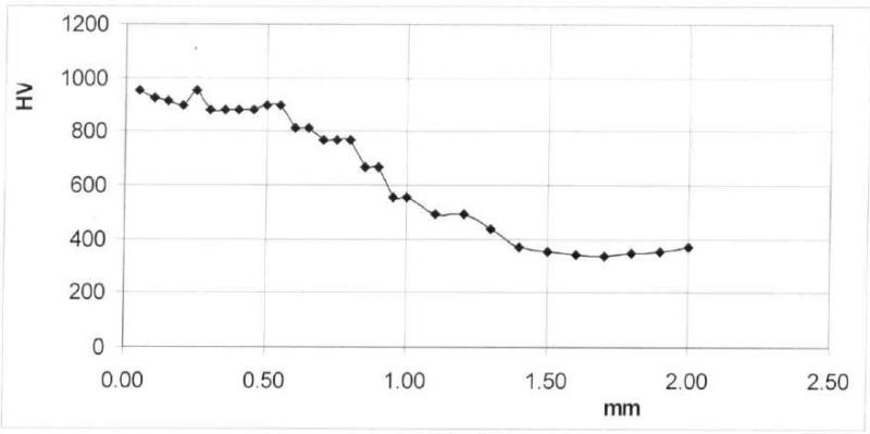
The gears were checked with two different Rockwell Hardness Testers and the result was always around 68 HRc. Then the gears were sent out to a laboratory for a material analyzis. They have reported a microhardness HV 0.8N (80G) at distance from the surface .05-2.0 mm as follows:

The chemical composition:

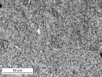
The surface layer structure:

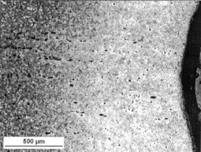
The surface layer:

Based on these results they have indentified the material as 17CrNiMo6 after carbourizing. A 1 mm thickness of the layer with minimal hardness of 550HV has been reported. They stated, that the maximum hardness of 940 uHV equals to approx. 68 HRc.
Any clues on how is that possible?

The chemical composition:

The surface layer structure:

The surface layer:

Based on these results they have indentified the material as 17CrNiMo6 after carbourizing. A 1 mm thickness of the layer with minimal hardness of 550HV has been reported. They stated, that the maximum hardness of 940 uHV equals to approx. 68 HRc.
Any clues on how is that possible?
- Thread starter
- #6
gearcutter
Industrial
I'm no steel expert but that doesn't look like 17CrNiMo6 to me.
Typically; Cr should be between 1.5 & 1.8, Moly 0.25-0.35, Ni 1.4-1.7 & Mn 0.40-0.60.
Typically; Cr should be between 1.5 & 1.8, Moly 0.25-0.35, Ni 1.4-1.7 & Mn 0.40-0.60.
- Thread starter
- #8
gearcutter
Industrial
While it doesn't solve the mystery, it does provide a hint that perhaps mistakes are being made.
Looking at a chemical composition chart for 17NiCrMo6 suggests that the composition of your sample still doesn't match what you're saying it should be.
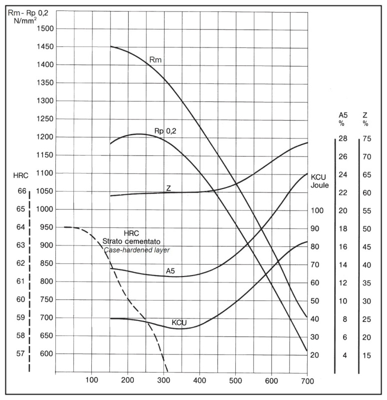
Looking at the tempering curves for 17NiCrMo6 below; it appears that the max un-tempered hardness is around 64HRC. I've no idea how 68HRC (equivalent) could be achieved.
That level of case hardness is usually associated with nitriding material such as 34CrAlMo5-10.
Has the Lab been able to give you an explanation?
I would suggest going over to the 'Metal and Metallurgy engineering Forum' and asking the question there, be careful not to make it look like you're cross-posting as your post might be deleted. -
I'm finding this really interesting, thanks for posting.

The hardness profile of the carburized case you posted shows a hardness of around Rc66 at a depth of .020", which seems unusual. The core hardness of around Rc35 at .080" seems about right, but I would expect the case hardness at .020" to drop more than just 2 points (68 to 66).
You might want to take a look at AGMA 2004-B89. It provides guidance on preparation of test specimens for checking the hardness profile of carburized gear teeth. You should pay particular attention to the length and diameter (L/D ratio) of the specimen required for the size of gear tooth you have, as well as making sure when cutting and polishing the specimen so that it is not overheated. Both of these factors can affect the accuracy of your hardness testing.
You might want to take a look at AGMA 2004-B89. It provides guidance on preparation of test specimens for checking the hardness profile of carburized gear teeth. You should pay particular attention to the length and diameter (L/D ratio) of the specimen required for the size of gear tooth you have, as well as making sure when cutting and polishing the specimen so that it is not overheated. Both of these factors can affect the accuracy of your hardness testing.
-
1
- #11
Well, this is an interesting example for reverse engineering. In order to achieve hardness in excess of 64-66 HRC, you have to do something different than conventional atmosphere carburizing (gas carburizing) or low-pressure carburizing (vacuum carburizing). Adding ammonia to the gas mixture during atmosphere carburizing is called carbonitriding, and can lead to increased hardness after quenching and tempering. Personally, I have never seen 68 HRC for this process, or even reported in technical literature, more like 65-66 HRC as a maximum. There are some treatments like ion nitriding that can create very high surface hardness, but usually the depth is quite small, not > 0.5 mm to 800 HV. If you are really interested in understanding what is going on with the sample, you will need some further testing that is quite specialized like elemental mapping of the near surface layer (SEM w/ EDS, maybe Auger analysis) and X-ray Diffraction.
- Status
- Not open for further replies.
Similar threads
- Locked
- Question
- Replies
- 1
- Views
- 1K
- Replies
- 2
- Views
- 2K
- Replies
- 11
- Views
- 13K
- Replies
- 3
- Views
- 740
