BracketMan55
Mechanical
- Mar 31, 2016
- 4
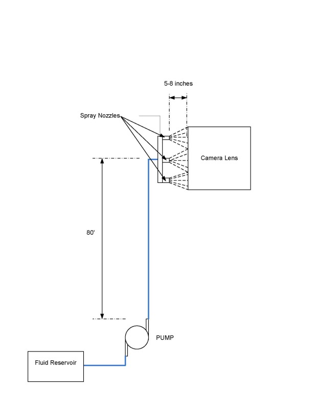
Hello all, I am a mechanical engineer working on a very particular application involving a fluid pump required to supply cleaning fluid (could be cleaning solution or just plain water) to a set of nozzles at the top of an 80 foot elevation. Attached is a layout of the overall system design overview.

In particular, we have a pump supplying pressure up a rubber hose to an elevation of approximately 80 feet. The fluid is then fed through a manifold and then sprayed through some nozzles to apply a cleaning action to a camera lens.
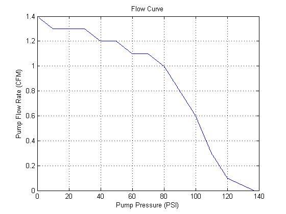
My question regarding this, however, pertains to the how we have been testing this set-up. In particular, we wanted to figure out if the pump we had was of a sufficient pressure to supply the cleaning fluid up the 80 foot elevation through the hose and then through the nozzle set-up such that it could provide a high enough spraying velocity to sufficiently clean the nozzle. When we did our testing, however, we did not have 80 feet of elevation to test the set-up in its desired configuration. It was then decided that a pressure regulator could be employed to drop the pressure in the hose by such an amount as to account for the 80 feet of head loss due to the elevation. Our question is, is this a valid approach? That is, is it justifiable from a scientific and engineering stand-point to simply exchange 80 feet of head for a pressure drop via a pressure regulator in the line (since we are using Bernoulli's equation to model this system for a compressible flow)? Does exchanging the head pressure for a pressure regulator cause any decrease in the velocity of the flow inside the line or a decrease in the flow rate? Also, does this exchange adversely effect the system curve in a way as to effect the flow rate? I have the pump curve for the pump we are using attached.

Thanks for all the help and expertise folks!
-Bracket Man

In particular, we have a pump supplying pressure up a rubber hose to an elevation of approximately 80 feet. The fluid is then fed through a manifold and then sprayed through some nozzles to apply a cleaning action to a camera lens.
My question regarding this, however, pertains to the how we have been testing this set-up. In particular, we wanted to figure out if the pump we had was of a sufficient pressure to supply the cleaning fluid up the 80 foot elevation through the hose and then through the nozzle set-up such that it could provide a high enough spraying velocity to sufficiently clean the nozzle. When we did our testing, however, we did not have 80 feet of elevation to test the set-up in its desired configuration. It was then decided that a pressure regulator could be employed to drop the pressure in the hose by such an amount as to account for the 80 feet of head loss due to the elevation. Our question is, is this a valid approach? That is, is it justifiable from a scientific and engineering stand-point to simply exchange 80 feet of head for a pressure drop via a pressure regulator in the line (since we are using Bernoulli's equation to model this system for a compressible flow)? Does exchanging the head pressure for a pressure regulator cause any decrease in the velocity of the flow inside the line or a decrease in the flow rate? Also, does this exchange adversely effect the system curve in a way as to effect the flow rate? I have the pump curve for the pump we are using attached.

Thanks for all the help and expertise folks!
-Bracket Man
