Eng-Tips is the largest engineering community on the Internet

Intelligent Work Forums for Engineering Professionals

Heat Loss Calculation for LP Steam Line

Status
Not open for further replies.

Pavan Kumar

Chemical
Aug 27, 2019
327
0
0
CA
Hi All,

I am trying to calculate the Steam condensate load for a low pressure steam line inlet to the control valve that feeds steam to the Steam bundle of the butane vaporizer ( please see sketch pasted below). This is to check the adequacy of the existing 1/2" TLV Free float steam trap. The trap has a capacity of 300 lb/hr at our operating conditions.

LP_Steam_Line_to_Butane_Vaporizer_Sketch_yvilqy.jpg


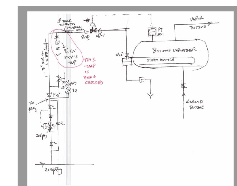
The inlet line to the control valve is 3" Sch 40 CS pipe that is 85 feet long with many bends in it. It is insulated with 2" thick mineral wool insulation. There is a 1/2" TLV SS3V-18 free float steam trap on the inlet line(see sketch). The LP steam is let down from the regulator from 265 psig to 70 psig. Due iso-enthalpic expansion the steam superheats and the temperature at the regulator outlet is 175.826 Deg C at 70 psig pressure(with 18.06 Deg C degree of superheat). The steam flow rate is 2660.6 lb/hr. I assumed the steam temperature to be constant at 175.826 Deg C through the entire line and calculated the heat loss through the pipe and insulation by considering

(i) resistance of the pipe wall ( very minimal)
(ii) resistance of insulation.
(iii) resistance of ambient air to remove the heat. Assumed the ambient air at 70 Deg F.

I used the following formulae for the heat flow through pipe, insulation and to the ambient air

LP_Steam_Heat_Loss_Equations_kbl8pk.jpg


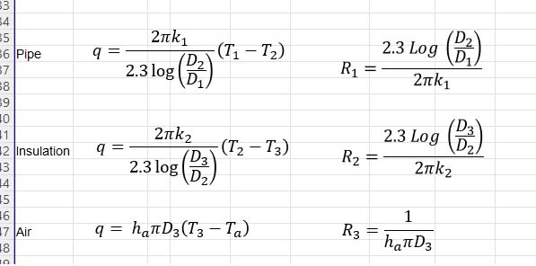
where D1, D2 and D3 are the pipe ID, OD and OD of the insulation respectively

T1 , T2 and T3 are the temperatures at pipe inside surface, outside surface and the outside surface of the insulation
R1, R2, and R3 are the resistances of the pipe wall, insulation and ambient air respectively.

After a few iterations I was able to calculate the heat loss to qLoss = 7935.2 lb/hr. The calculation spreadsheet is attached with this post.

The specific enthalpy of superheated steam at 70 psig and 175.826 Deg C is 1202.748 Btu/lb . With flow rate of 2660.6 lb/hr the heat load of steam is 2660.6*1202.748 = 3200019 Btu/hr. Subtracting the pipe heat loss of 7935.2 Btu/hr dividing the result with the steam flow rate the specific enthalpy of steam at the control valve inlet is 1199.8 Btu/lb.

There is a pressure drop of 13.52 psi in the inlet line to the control valve. So the pressure at the control valve inlet is 56.48 psig. Checking the steam condition with P= 56.48 psig and specific enthalpy of 1199.8 Btu/lb in the steam tables, I find that the steam condition is still superheated with a temperature of 169.9 Deg C with a degree of superheat of 18.8 Deg C. This means that there should not be any condensation. But we do see condensate coming out of the tarp in operation. I can see the condensate as the trap is leaking right now. This means my calculation is not correct. I want to correct my calculation and hence this post. I request your help in this regard.

Thanks and Regards,
Pavan Kumar

 
Replies continue below

Recommended for you

I looked over your calculations and cannot find anything wrong. I did not do a rigorous heat transfer calculation but you can find charts on internet with generic 2" insulation on various pipe sizes and various delta T's. On engineering toolbox one such chart gave 85 BTU/Hr-ft, which is very close to what you calculated. Also you appear be calculating the conditions just upstream of the control valve correctly, and any addtional pressure drop you calculated does not seem unreasonable in the pipe and would just increase the superheat - but appears very high so you must have very high velocity.

My guess is that the steam off of the header is not saturated and is below saturted temperature and has a lot of entrained condenstate. When the steam plus condenstate passes through the regulator, the condensate will tend to flash into steam by using the heat content of the condensate itself above saturation, plus the heat of the steam above saturation for the required latent heat of vaporization of the entrained liquid. However, not doing the rigerous calculation myself, I assume there is not enough sensible heat available in the %condensate and %steam to vaporize the entrained condensate. In addition due to high velocity and very little time for heat transfer from the superheated steam to the entrained condensate any available heat in the %steam is mostly not availalbe. So basically the condensate is the remaining entrained condensate that was there upstream of the regulator.

Is there a trap on the mainline upstream of the regulator that can efficiently remove condensate? If no maybe need one.

 
Pavan,

A couple of things,

One, just because you can get a calculation or a table to give you answers to three decimal places, doesn't mean you should list them like this as otherwise you can get confused with the numbers and things are simply not that accurate. you can easily loose sight of the meaning of the numbers.

Two - That pressure drop is just insane. The velocity must be nearly sonic velocity so your system isn't going to survive that long.

Is this a working system?
Can you get actual numbers like pressures and temperatures to use / compare?
Is the insulation as good as you assume?
The heating capacity translates as 950kW. This seems rather high, but maybe steam systems can give you that - not my normal field.

Remember - More details = better answers
Also: If you get a response it's polite to respond to it.
 
Hi LittleInch,

Please see my response below. I also attached my pressure drop calculation spreadsheet. Please see the tabs "Steam Inlet DP Calc-1" and "Steam Inlet DP Calc-2" for the calcs for the inlet line.

Thanks and Regards,
Pavan Kumar

LittleInch said:
A couple of things,

One, just because you can get a calculation or a table to give you answers to three decimal places, doesn't mean you should list them like this as otherwise you can get confused with the numbers and things are simply not that accurate. you can easily loose sight of the meaning of the numbers.

Ok.

Two - That pressure drop is just insane. The velocity must be nearly sonic velocity so your system isn't going to survive that long.

The inlet has the following fittings

1) 1" Tee - 1
2) 1"X3" conc reducer - 1
3) 85 feet of 3" Sch 40 pipe
4) 3" 90 degree elbow - 7
5) 45 Degree LR elbows - 2
6) Tee thru run - 1

The pressure drop in the 1" Tee and 1"X3" reducer is 12 psi, while the pressure drop section is just 1.6 psi making the total pressure drop to 13.6 psi. The velocity in the 1" section is 700 ft/sec while that in the 3" section is 95 ft/sec for a mass flow rate of 2660.6 lb/hr of superheated steam.

Considering adiabatic flow ( in reality it is polytropic) the sonic velocity works out to be 1722.6 ft/sec. So the Mach numbers in 1" section are Ma = 0.4 while in 3" section is 0.055. The velocity is not sonic. All the pressure drop is in the 1" Tee thru run and the 1"X3" reducer as the velocity is very high. I checked with AFT Arrow and results were close. I will check once again.

a = SQRT(gc*r*R*T/M)
= SQRT(32.17*1.33*808.48/18.015) = 1722.6 ft/sec

where,
a = speed of sound in the medium.
gc = gravitation conversion constant = 32.174 lbm-ft/sec2-lbf
r = Gamma = ratio of specific heats. for steam Gamma = 1.33
R = Universal gas constant = 1545.2 ft-lbf/lbmole-Deg R
T = vapor/steam flowing temperature = 808.48 Deg R (=175.826 Deg C)
M = Molar mass of steam = 18.015 lb/lbmole


Is this a working system? No. The current line size is 1 1/2" Sch 40. I am changing it to 3" Sch 40 due to high pressure drop in the 1 1/2" line.

Can you get actual numbers like pressures and temperatures to use / compare? There is just one pressure gauge downstream of the pressure regulator that is used to set the let down pressure and thats it. No other pressure gauge or transmitter to check the pressure drop.

Is the insulation as good as you assume? The 2" thick mineral wool insulation that will be installed on the 3" pipe will be new and I hope it will be good enough.

The heating capacity translates as 950kW. .This seems rather high,
Heat loss of 7935.2 Btu/hr translates to 2.32kW ( 1 Btu/hr = 0.000293 kW)

but maybe steam systems can give you that - not my normal field.
 
 https://files.engineering.com/getfile.aspx?folder=41ec2322-d87c-4697-961b-fbedf3959923&file=1.__Steam_Control_Valve_Pressure_Drop_Calculation_-_Max_Flow.xlsx
@Pavan Kumar
For your info
1/ Many pipelines simulators have an in-built comprehensive heat loss module, e.g. see Inplant/Pipephase.
2/ Your heat loss calculation is related to nominal resistance and does not consider insulation deterioration. So it is valid only for first several years after start-up.
3/ Your heat loss calculation does not consider wind and humidity of air.
4/ This type of calculation is quite obvious and well known. What is the reason that pushes you to go through this road one more time (rhetorical).
5/ Insulation resistance is a result of a feasibility study "capex vs opex" as heat loss means money loss. Several cases modelling of optimum insulation type and thickness might be required for several climate conditions (e.g. mild, severe, storm).

More links to support your work
 
Hi shvet,

Thank for your replies and asking me the right questions. Here are my replies.


1/ Many pipelines simulators have an in-built comprehensive heat loss module, e.g. see Inplant/Pipephase. Ok. I will check if AFT Arrow can do it.

2/ Your heat loss calculation is related to nominal resistance and does not consider insulation deterioration. So it is valid only for first several years after start-up. I agree. I am going to install new insulation on the new 3" line that I am installing.

3/ Your heat loss calculation does not consider wind and humidity of air. Yes I agree. Can you point to the references that factors these so that I can work out the calculations. That will be great help.

4/ This type of calculation is quite obvious and well known. What is the reason that pushes you to go through this road one more time (rhetorical). The reason for my doing heat loss calculation is that there is a steam trap on the line that needs to be rated. The existing line was 1 1/2" Sch 40 which I am upsizing to 3" Sch 40 due to pressure drop reasons. Bigger line means higher heat loss and greater the condensate load. I want to re-use the existing 1/2" TLV Free float steam tarp on the 3" line with suitable reducers. I want to check if this trap is still adequate. The 1/2" TLV steam tarp that I want to re-use has a capacity of 300 lb/hr.

5/ Insulation resistance is a result of a feasibility study "capex vs opex" as heat loss means money loss. Several cases modelling of optimum insulation type and thickness might be required for several climate conditions (e.g. mild, severe, storm). I fully agree. At the moment I only want to make sure that the insulation thickness is less than the critical radius forumula mentioned in DG Kern book first edn page 30/378. My heat loss calculation is based on the theory in DQ Kern pages 17-19.

More links to support your work

This link gives only the radiant heat loss, how about conduction heat loss from the steel and insulation and the convection heat loss from the ambient air. Also I want to ask you does the steam flow rate inside play a role in the heat loss?. Intuitively I think it should not as the convection only makes the pipe inside temperature same as the steam temperature. Please correct me if I am wrong. Based of my calculations I find that when superheated steam enters the pipe at 70 psig and 175.826 Deg and flows through 85 feet of 3" Sch 40 pipe the steam quality at the end of the pipe is still superheated with pressure of 56.48 psig and temperature of 169.9 Deg C. This means no condensation but I see condensate coming out of the leaking trap. @Snickster pointed above that this condensate could be from the main steam line that is getting carried over. What is your opinion?.

Thanks and Regards,
Pavan Kumar
 
@Pavan Kumar

This is the reason many engineering companies relies on software - that helps to save man-hours (money), reduce schedule and submit stable and reasonable results. Note that as per my experience in some companies software budget got 1/3 of company gross expenditures.

Manual searching and calculations kind of you are currently working on lead to waste of one's time while results are readily available by outsourcing by a bunch of software developers. This is a worthy example of exercises related to upgrading one's engineering skills and a subject of loss of profits related to one's money making. As I understood your replies now you are in second position so I recommend to find a software/spreadsheet that makes those calculations better than you do as otherwise you will obtain no more than any newcomer will do from a dedicated handbook. Heat loss modelling has been studied, published, criticized, restudied, republished and so on every couple of years as the issue is quite simple, obvious and related to classic heat transfer. You can find a lot of info in your favorite searching engine - an example.

As per my experience pipeline modelling software like Inplant/Pipephase do this work quite well.
 
HI shvet,

Yes of course using software would be very stable and reliable. But I would like to calculate it through first principles too.
I will use AFT Arrow (this is what we have here) and check if I can use it calculate the heat loss.

Thanks and Regards,
Pavan Kumar
 
@Pavan Kumar

Note that your model ignores:
- "bridges of cold" like supports, valve bonnets, thermowells, instrument connections, bounding&earting
- flanges which normally are naked
- insulation of valves which normally is ununiform or even quick-release design

That means that long-distance piping, e.g. main inside of a piperack, is able to be predicted properly by this model while complex piping, e.g. control valves, traps, manifolds, is not.

Note that resistance of insulation+airside is critical. Resistance of pipe wall+steamside may be neglected with reasonable results.

Let me remind one more time that this calculation is valid only for first several years in operation until insulation will not deteriorate.
 
Hi, I've been offline all week. I'll share a quick calc from a previous company's design manual.
Capture_gwwz68.jpg

[Δ]T = 176 - 21 = 155[sup]o[/sup] C = 279[sup]o[/sup] F
U = 0.78 Btu/hr/[sup]o[/sup]F/ft[sup]2[/sup]
A = [π]D[sub]o[/sub]L = 3.14 x 7/12 ft x 85 ft = 156 ft[sup]2[/sup]
Q = UA[Δ]T = 0.78 x 156 x 279
Q = 34,000 Btu/hr
W[sub]condensate[/sub] = Q/[λ] = 34,000/(1203 - 287) = 37 lb/hr
Pavan Kumar said:
The trap has a capacity of 300 lb/hr at our operating conditions.
[2thumbsup]
Note - Steam traps are often sized for start-up conditions and some acceptable duration.

Good Luck,
Latexman
 
Hi shvet,

I have considered convective resistance of air in my calculation. I will run the model in AFT Arrow once I have some IT issues resolved.

Thanks and Regards,
Pavan Kumar
 
Hi Latexman,

The table you shared is very helpful. Would it be possible to email me this cut sheet with the relevant pages of the manual.

In you calculations you took Do= 7" , it is actually a 3" pipe. The OD is 3.5 inches.

Ao = PI()*(3.5/12)*85 = 77.92 ft2
With this I get Q = 0.78*77.92*279 = 16956.95 Btu/hr

Please let me know how you got the heat of vaporization value of 1203-287 = 916 Btu/lb

Thanks and Regards,
Pavan Kumar


Hi Pavan,

I sent the e-mail with attachment. Did you get it?

Yes, I realize it says "(Based on Outside Pipe Area)". You may be right, but on insulated lines I've always used the bigger more conservative number, the outside diameter of the insulated pipe. And, yes, I did it fast and sloppily, 3" NPS + 2" insulation + 2" insulation = 7". I left that company in 2001, so I can't ask the guy that wrote that section for advice. Sorry.

On heat of vaporization + superheat I used your "1202.748 Btu/lb" of the superheated steam and subtracted the enthalpy of the sat'd liquid at 70.3 psig, 286.55 Btu/lb, from Crane TP410. I didn't know what reference you were using, but . . . that's what I did.

Good Luck,
Latexman

 
Status
Not open for further replies.
Back
Top