Continue to Site

Eng-Tips is the largest engineering community on the Internet

Intelligent Work Forums for Engineering Professionals

  • Congratulations GregLocock on being selected by the Eng-Tips community for having the most helpful posts in the forums last week. Way to Go!

HEAT PUMP OPERATION WITH SWIMMING POOL

Status
Not open for further replies.

moideen

Mechanical
May 9, 2006
360
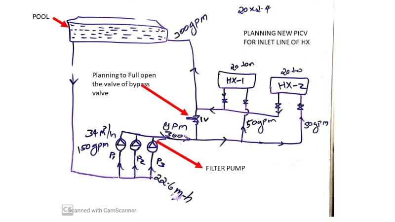
I have an existing 2 no swimming pool heat pump, both are locally manufactured , so there is not any datasheet available to know the design flow rate. Manufacture told and compressor datasheet says that both rated with 20 ton (total heating capacity 200 kw). the flow rate can assume 50 gpm per unit( ton *2.4 gpm)The issues related with the coincide operation of pool filter pump. The Heat pump hasn’t dedicated pump, but using the same flow of filter pump.
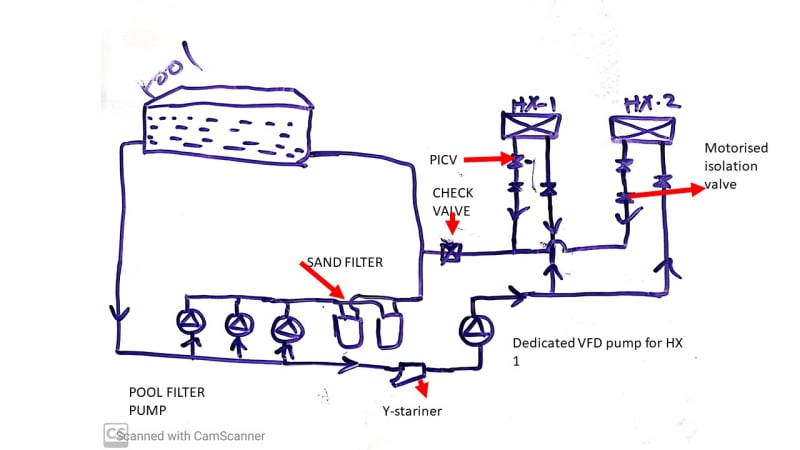
The filter pump’s flow rate is 300 gpm which circulate through the heat pump, for heat pump its maximum flow 50 gpm(11m3h) only per unit. As per the present scenario circulates 300 gpm(68m3h) through HX. The Situation goes to worsen that high pressure water is bleeding from pipe fittings when close the valve of any heat pump. I attached the hand sketch of pipe’s schematic.
I want to plan open the bypass valve completely and fit a PRV on the line into the heat pump, and two picv for individual circuit of HX. helpful comment is appreciated. Thanks
pool_shematic_aei7h2.jpg
 
Replies continue below

Recommended for you

If you fully open the bypass then why would any water want to flow through the heat pumps? You'll get very little flow through the heat pumps.

Also if you want control flow then you need some way of controlling on flow or measuring flow.

On the bypass a simple orifice plate should give you a small but sufficient differential pressure to force some flow through the heat pumps. Then just install a control valve of some sort on the heat pumps outlet and measure flow. Once set up this shouldn't change much. Even if you shut off a HX, the flow through the other should only increase marginally and most of the excess go through the bypass.

Might need a bit of iterative design.

Or could you just pipe the HX through one pump? 75 gpm each should be ok but you could throttle back one of the pumps a little bit and trim each HX to get your ~50 GPM. Might need a separate manifold to be able to use any one of the three pumps, but not really that hard and much simpler.

Remember - More details = better answers
Also: If you get a response it's polite to respond to it.
 
littleinch: thanks for the response. As your advice and in the perspective of enegy saving , better go with dedicated VFD pump like I attached the schematic. For this, select a new VFD pump with 100 GPM with same head of filter pump. The vfd would varies the pump when isolating any hx from load. One issue is that the heat pump now receives the flow after the filtration by sand filter of pool purpose. for filtration, a Separate y strainer need to be fixed.check valve will preven back flow from pool water. thanks


pool_shematic-3_lzkfuy.jpg
 
You can attach the suction of the HX VFD downstream the sand filter but u/s the HX discharge point.

This is then just a secondary loop. Head is quite low, but this is a very common HVAC arrangement. You then don't need the NRV. You probably don't need the same head as the filter pumps - just enough to get 50 GPM through the HX. where will the VFD get it's flow input or differential pressure control?

remind what a PICV is.

If you want to stay as you have then you should always place filters downstream of the pump to avoid starving the pump of water.

Remember - More details = better answers
Also: If you get a response it's polite to respond to it.
 
You already have a pump. You shouldn't need another pump. Just put a ball valve in the main line after the filters. Put a tee before and another after the ball valve. Just close the ball valve a little to cause enough differential pressure to make the desired flow rate go from the first tee to the heat pump and back to the second tee.
 
I agree with Vc! Do exactly what you did with your first drawing; put in a bypass with an adjustable valve. Put a sight flow gauge in each HX loop. Adjust the valve with an eye to getting 50GPM thru both HX. That's it. You sure don't need more pumps and filters and maintenance and operating costs.

Keith Cress
kcress -
 
Gas fired Pool heaters for decades have an internal bypass to limit the flow through the coils to the proper amount using a spring and poppet valve in a seat cast into the header manifold. I would assume any heat pump replacement have the same device. A residential pool heater would be able to operate from 5 gpm to 50 gpm without issue automatically.
In cases where a residential heater was installed on a commercial application the 2 tees and bypass valve was used with just a slight closing of the bypass valve
Since flow meters are expensive, the slight closing of the valve was set with the system in operation, close the bypass valve when there is a slight temperature increase between the inlet and outlet on the heater lines and lock the bypass valve in that position.
here the calcs
50 gpm is 420 lb/min or 25,200 lb/hr
1 btu = raise 1 lb of water 1° F
20 ton is 240,000 btu/hr
So the temperature on the outlet should be ~10°F (~6°C) warmer that on the inlet

I was a swimming pool repairman during high school and college.

Hydrae
 

Thanks for littleinch, Valvecrazy, itsmoked:
The existing bypass valve is ball valve in the first drawing. Ball valve is not like a balancing valve or DRV. Cannot lock the position of valve handle of ball valve. so, there is a chance a hand working on this valve like closing and opening insensitively cuz different teams come to the plant room for pool maintenance. One heat pump will be switched off after gaining the pool’s set temperature. Then one heat pump will come to the line and second will act as a standby mode. It is part of energy conservation program. For this purpose, automatic isolation valve needs to be placed on both hx water circuit. So, I think to install a DRV instead of ball valve after the sand filter(we can lock the handle if it is DRV). Once DRV set after ensuring the flow rate of both HX are 100 gpm . but, after switch one HX, additional 50 gpm will also be circulated and subsequently pressure also increased. This is a remaining issue to be cleared
Littleinch: PICV-pressure independent control valve, it regulates the flow irrespective of pressure exerted in the pipeline.
 
Status
Not open for further replies.

Part and Inventory Search

Sponsor