Hi!
I have a problem and it is the following:
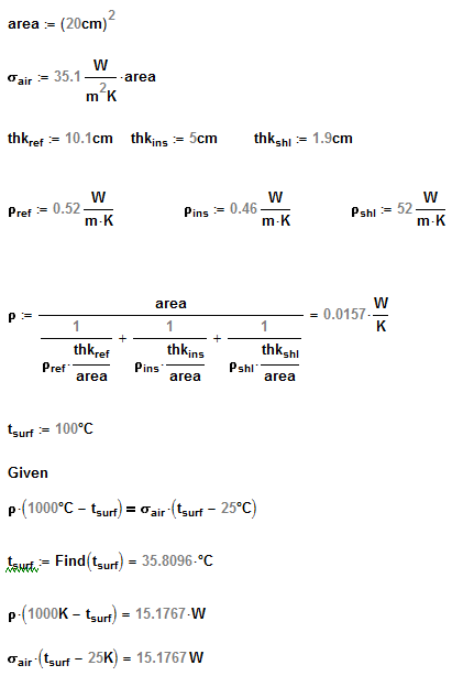
There are 3 plates of 20cm x 20 cm x 10cm (for refractory) , 5cm (for insulation), and 1.9cm (for Shell)...as per attached image. In one face, the hotter face, there is a temperature (ti) of 1000°C. Taking into account the following thicknesses of each material...I want to know the final temperature of the coldest face considering that in the coldest face has a initial temperature of 25°C and the air is flowing through that coldest face.
The thermal conductivity of each material is as follows:
(refractory = 0.52 W/m*K, insulation = 0.46 W/m*K, and Shell = 52 W/m*K)
I used SOLIDWORKS SIMULATION to solve this problem. When I give the THERMAL LOADS to each face, I begin with the known temperature and it is the hotter face (1000°C = ti) but for the coldest face I give a CONVECTION ISSUE as thermal load but SOLIDWORKS asks me for two parameters:
-Convection Coefficient and Bulk Ambient Temperature.
I consider that air is flowing through coldest face so I put 25°C in BULK AMBIENT TEMPERATURE but for convection coefficient...I had problems with that part.
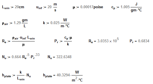
I found on engineering toolbox web site of a empirical formula to know the convection coefficient or convective heat transfer coefficient of air when air velocity is from 2 to 20 m/s and it is the following:
- hc = 10.45 - v + 10 v ^1/2. (V = m/s speed)
I used 20 considering standard value and the value was 35.1 W/m2*K.
The software solved the solution and tf (final temperature) was like 90-100°C. I want to know if what I did was correct or what steps I did wrong.....hope you can help me how can I be sure that I am in the correct path
Thankyou
Roland


