Eng-Tips is the largest engineering community on the Internet

Intelligent Work Forums for Engineering Professionals

  • Congratulations waross on being selected by the Tek-Tips community for having the most helpful posts in the forums last week. Way to Go!

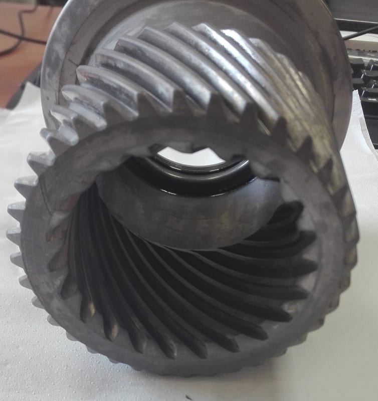
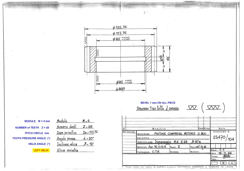
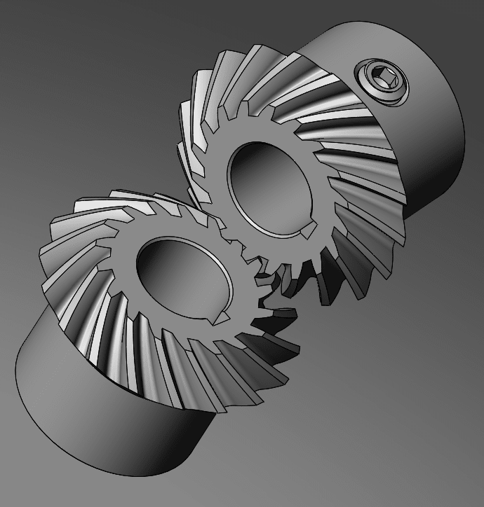
helical gear, multi-start thread drawings 2D - how to make it ? 2

Status
Not open for further replies.

Blondys

Mechanical
Apr 19, 2020
4
0
0
PL
Hello,
I am searching a sample technical drawings for helical gear or multi-start thread (I mean single element; for example: gearwheel or pinion)

exactly: how to make the correct 2D drawing for this, picture below


90d3444545971e709a0daa71d883b263_d2vg1i.jpg


thanks in advance
 
Replies continue below

Recommended for you

Get your hands on some old paper catalogs from power transmission companies like Browning, Morse, Boston Gear, Falk Gear, and many others. You will see examples of how engineers used to accomplish these things before the days of 3D modeling. This is an example of where the technical notes on the drawing convey more meaning than any graphical presentation.
 
Blondys,

3D[ ]modelling a helical gear or multi-start thread is somewhat difficult, especially if you plan on some form of rapid prototyping. If this thing is to be machined, a worker is going to select a tool. Your 2D[ ]drawing must indicate what form you want and what standard it must meet. When I worked on a drafting board, I never drew all the teeth in. It was a waste of time.

M5X0.8 - 6H THRU

Look in your Machinery's Handbook and see how many pages are required to describe the form, dimensions and tolerances of a metric thread like the one above. The same goes for Unified National threads. Formal specifications and tools are there for a reason.


--
JHG
 
Can confirm, lots of complex surfaces like gears, threads, knurls, on and on that for a designer that's using the process, there's no need to model but to look busy or satisfy some boredom. If you're meshing gears, define pitch max and pitch dia on your model and note the rest.

My dad did tell me, maybe 95 or 98 someone came and talked at the design course he taught and mentioned the 3d printed a differential for a prototype and it worked well once run in.
 
moon161,

I need to read up on modelling involutes. I designed a parametric gear in SolidWorks. I went to my 1941 edition of French's Engineering Drawing, and I followed the instructions on how to draw gears. We FDMed some of the gears, and they worked nicely. At 32DP, French's tooth form was close enough to an involute form, that much of the error actually was due to the FDM process.

--
JHG
 
First draw a sketch of your involute gear.
Copy it around an axis 360 degrees with the number of teeth you need.
Then sketch a path you want the sketch to follow.
Extrude along that path.

Drawing involutes is easy if you know what they are. Otherwise there are some formulas on the Google.

Spiral_bevel_u3p5ln.png
 
Blondys-

You can download a copy of MIL-HDBK-400 here: Link Section 5.1.4 covers engineering drawing requirements for an external involute helical gear. Below is a sample engineering drawing of a component with an external helical gear and an external involute spline.

Capture_1_szavvz.png
 
Status
Not open for further replies.
Back
Top