Continue to Site

Eng-Tips is the largest engineering community on the Internet

Intelligent Work Forums for Engineering Professionals

  • Congratulations KootK on being selected by the Eng-Tips community for having the most helpful posts in the forums last week. Way to Go!

Helical gear teeth deformation due to high rotational speeds - ANSYS

SMKRe

Mechanical
May 17, 2023
44
reference.jpg


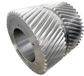
reference image used in the static structural analysis. I have carried out analysis in ANSYS for calculating the gear tooth deformation for various pitch line velocities. gear tooth is expanded/ deformed as shown below. Why the gear tooth is not having the same deformation across the face width due to centrifugal force (because of high rotational speeds)?
could any body tell why the deformation is more at center and compared to end of the teeth.


Centrifugal - radial deformation.JPG

along the gear tooth face width face width the deformation is maximum the outside, no deformation at around 1/3 from inside and again deformation
 
Replies continue below

Recommended for you

View attachment 2679


reference image used in the static structural analysis. I have carried out analysis in ANSYS for calculating the gear tooth deformation for various pitch line velocities. gear tooth is expanded/ deformed as shown below. Why the gear tooth is not having the same deformation across the face width due to centrifugal force (because of high rotational speeds)?
could any body tell why the deformation is more at center and compared to end of the teeth.


View attachment 2678

along the gear tooth face width face width the deformation is maximum the outside, no deformation at around 1/3 from inside and again deformation
OP
Normally it is optimal to have the slightly centered.
Having high RPM and High torque values
Induces tooth bending and deformation
And it is a very complex issue. There is no simple answer. Start with the material and it's mechanical and metallurgical properties.
Cand take the above loads at the required rpm.
Secondly the desired mod or diametral pitch
And pressure angle, as well as the gear tooth involute and lead. May require modification.
As well as the contact stress , lack of hardness on the gear teeth faces. Or the lack of the correct oil lubrication.
Heat is the enemy. Improper lubrication self destruct a gear. One mor r tip is the required quality AGMA or Iso. , surface finish will also effect coefficient of friction.
 
I guess that whatever boundary conditions you've applied dictate the result that you've gotten.
 
Regarding Boundary conditions:
Only two boundary conditions.
I have given cylindrical support at the journal bearing bearing centers. (tangential is free, axial&radial - fixed).
Rotational speed (RPM) is given.
load is not considered (no-load)
 
Is this a tool trying to sell a product. Duh
I am not selling any product. I am asking the reason for more deformation at middle of the gear teeth because of rotational velocity
 
Last edited:
OP
Please advise the input and output torque, rpm
, Gear data of the gear train . Material used for design, and heat treat .
 
OP
Please advise the input and output torque, rpm
, Gear data of the gear train . Material used for design, and heat treat .
The first image is shown for understanding only (representation of double helical gear).
For my project work, I have considered material as structural steel. I have not considered heat treatment. load is not considered.

The objective of the work is to calculate the gear teeth deformation because of high rotational speeds. dia of gear is 300mm and one side face width is 200mm
 

Part and Inventory Search

Sponsor