Eng-Tips is the largest engineering community on the Internet

Intelligent Work Forums for Engineering Professionals

Help designing a dimmer 3

Status
Not open for further replies.

LucasBS

Mechanical
Jun 4, 2010
79
0
0
BR
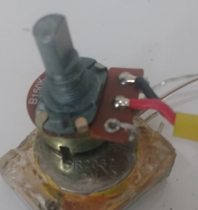
I need to design a dimmer, but I'm having a problem with the potentiometer, that heats up too much

It's 150k, and it's practically impossible to get a different one

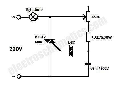
The same problem goes to the diac/zeners: also difficult to get a different one. Right now I'm using the DB3 diac, that conducts after 31V, symmetrically.

No limitations on the capacitor, however: any values I have available.


Adding insult to the injury: the dimmer must work with it's whole excursion: from cutoff to maximum.

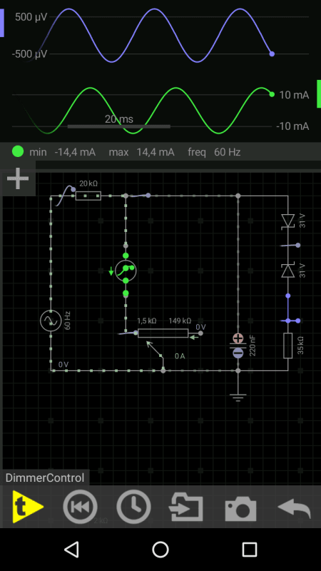
Cutoff is easy: around 5mA passes through the potentiometer, so the voltage on the node stays below the 31V

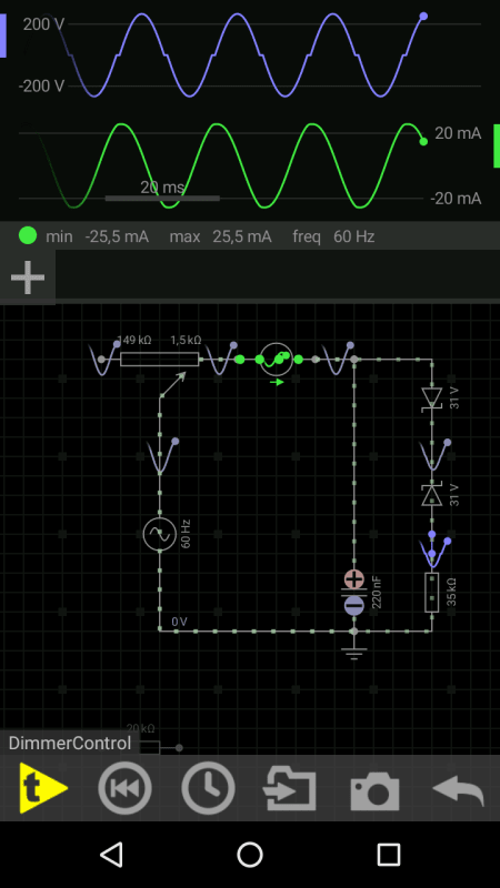
Saturation is hard: around 20mA passes through the potentiometer. Stinks instantly.

I could not think/simulate any arrange of resistors that could do this trick
Anyone with a solution or similar experience ?
 
Replies continue below

Recommended for you

Got a schematic? You can post it using the
ice_screenshot_20160718-141231_ejl13e.png
above.

Keith Cress
kcress -
 
120 or 240 V? Or any other voltage?

Can't understand the problem. Dimmers exist for decades and decades and I used to design such circuits before we replaced them with PIC and Texas Micro controllers. Potentiometers can be had at any suitable value, 1 Megohm is common. Do size limitations make it difficult/impossible to use a 1 or 2 W potentiometer?

Gunnar Englund
--------------------------------------
Half full - Half empty? I don't mind. It's what in it that counts.
 
220V

Availability is the problem
I live in a small town of a sh!t country, and it takes 40 fold or more the price of the pot to ship one of these
I could accomodate a bigger pot, but it would be a lot of plastic breaking and glueing

But was it 1M ohm, wouldn't it suffer the same problem (high current when the resistance is low)?

This pot came from the same circuit I'm trying to replace. But the original used many glass SMD diodes. Due to size, I'm unable to read their values, so the best I can do is build another from scrath
 
"wouldn't it suffer the same problem (high current when the resistance is low)?"

You need a resistor between wiper and Diac. And I hope that you use the potentiometer as a voltage divider and not as a series resistor. If the latter: No Luck. Will not work even with a 1 Mohm potentiometer. What wattage is the present potentiometer?

Gunnar Englund
--------------------------------------
Half full - Half empty? I don't mind. It's what in it that counts.
 
The following pictures are from a simulation. The result/values are very close to reality.

(Excelent and lightweight simulator, by the way: EveryCircuit)

This first picture here is the ideal: Works well from cutoff (not depicted) to span (as represented).
Ideal_ahav92.png


But you can see the current... Enough to fry the pot

This second one here is the voltage divider.
It cuts off well (500uV doesn't activate the triac), but it chops up the full wave (not depicted).
Divider_tcxf2p.png


And... The current did not reduce much

Changing the fixed resistor or changing the capacitor messes with either cutoff or full wave (or both, if I stick a resistor in series with the pot).


I don't know what else to do.
If someone tells me it's impossible, I might believe


I'm unable to tell the supported power of the pot, but if knowing the size helps, it's one of those 3/4 of inch
Pot_pncyyt.jpg
 
OK. But don't quite get it. You are using Zeners instead of a Diac. Those two Components behave rather differently. So the simulation doesn't say what the real circit does.

Also, the peak voltage is just above 200 V. That would indicate an RMS value at about 155 V AC. That is a voltage that I have never seen, anywhere. If you have 220 V AC, then your peak voltage should be around 310 V.

A few sample Circuits below (just googled "dimmer circuit" and got hundreds of them). Note that there is always a current limiting series resistor to avoid overloading the potentiometer when at maximum. Without it, or a voltage divider connection, your pots won't live long.

image_xdwc5f.png


Standard Circuit. With series resistor and diac.


image_foz2nn.png


Circuit that depends on extra (fixed) delay in C21, the voltage divider action (R3) and the Triac Gate's sensitivity to set conduction angle. May be easier to get Components for. But generally not as stable as the Diac version.


Gunnar Englund
--------------------------------------
Half full - Half empty? I don't mind. It's what in it that counts.
 
I've been trying to explain the low peak voltage and found out that a series of factors lead to it, being the series resistor (even a small resistance reduces the voltage that much, depending on the arrangement), the capacitor (it has a resistance in AC, therefore producing a divider), and finally, the zeners (the point where this ~200 volts is being measured is AFTER them).

Too bad the simulator doesn't have diacs and triacs. But is there so much difference, mind asking ?

I'm so far from success, that such a precision feels like a consern for much later.

Anyway

In this same simulator of mine I reproduced the first picture you posted. It works great. Gave me hope for a minute

Problem is the values: it's easy with a 600k pot, but it's not with a 150k
And I tried to tweak the other components. Same outcome: it either doesn't reach the cutoff or doesn't reach the possible maximum
If I increase the capacitor, it takes more current to fully charge it. Good for cutoff, bad for span. And vice versa
The same happens if I increase the series resistor

No success on your second schematic either. It falls under the same logic of the voltage divider attempted before: "more mouths to feed" (more capacitors and resistors draining current from the pot to the ground)


Is there another arrangement of components not attempted yet ?
One that takes into account these particularities here (specially the low resistance pot) ?

You must be tired, but....WHAT IF there is one, right ?

If not, I'm gonna open the pocket. Enough wasting your time and mine
 
I may find one of my old (from the eighties) design. I have got rid of lots of stuff but if I find it, I'll make a picture of it. Hole mounted and large components, so easy to read. Would a few Amps fit the bill? Or more needed? No pocket, please.

Gunnar Englund
--------------------------------------
Half full - Half empty? I don't mind. It's what in it that counts.
 
Um.. 40 A is the toughest triac there is. OK, you may find one or two rated at 42 A, but there is no margin if more is needed. You may have to use a thyristor (SCR) instead. It is possible to get away without gate transformers or ganged potentimeters if you put the SCR in the diagonal of a rectifier bridge. The extra losses in the bridge will be around 10 W and that is, in my view, OK if your rated load is around 8000 W. There are also rectifier blocks, but they need isolated gate drives. Or ganged potentiometers, which is a terrible thing to have. Really.

Your question about Zener vs Diac. No, they are not the same thing. A zener starts conducting at, say 30 - 35 V and then keeps that voltage until input gets below it. A Diac discharges like a flash when it gets above the break-down voltage, which usually is also 30-35 V, and transfers all of the energy in the "delay" capacitor to the Gate. Thus ensuring efficient turn-on. The zener Circuit is dependent on the available current (seldom more than milliamps) and will not gate the triac on.

That is also why you fry your potentiometers. If the triac does not turn on, you will have all voltage left to fry the potentiometer. When it turns on, the voltage drops to one or two V and that saves the potentiometer.

Sorry, but a 40 A dimmer will require a lot more than I thought that this thread should lead to. It is also very important to know if the load is purely resistive or if there are inductive components present. Or capacitive, which is also a problem because of high charging currents that kill the triac. Even a purely resistive load may be a problem if there is a high ratio between hot and cold resistance. Tungsten lamps can easily have a 10:1 ratio and a rated current equal to 40 A will then be a momentary 400 A surge. Semiconductors are not like motors or transformers and will die after a few cycles at 10 times rated current.

There are commercial units available. Have you looked at them?


Gunnar Englund
--------------------------------------
Half full - Half empty? I don't mind. It's what in it that counts.
 
There are the SanRex triacs. Seem to be available up to 70 A with around 600 A surge capability. Should work in your application. Gate sensitivity is like most other triacs.

Tested a similar one, TG36C, and it works fine with a diac, a 220 nF capacitor and a 1 Mohm potentiometer. I think that you can take it from there. Don't forget the di/dt limitation. Or you will fry the triac instead ;)

Gunnar Englund
--------------------------------------
Half full - Half empty? I don't mind. It's what in it that counts.
 
>Big correction: it's around 31A (7kW)<

BTA41 is the triac currently present in the circuit I intend to rebuild.

I don't know if the triac is the faulty component, but if it is, an overtemperature might explain the defect. Followed by the spikes caused by the diac.

The good news is that it is water cooled
This circuit, I should've informed from the beginning, is a controlled water heater.

So, resistive then.

31A is far from the BTA41's capability. That means I don't need to work the whole sine wave

This probably resolves this thread AND explains how the manufacturers made it with a small potentiometer


The bevavior of the diac you described also explains a lot
And I intend to deal with SCR for personal applications in the future. Those tips are useful and might explain surges I experienced when I started learning about dimmers some time ago


Thank you for everything so far
 
Triacs and SCR will heat up quite a bit even when operating properly. Back to back SCR are generally used over 20A. Forward voltage is always about 1.5V. Multiplied by 40 so amps is a lot of heat. Good thing you are water cooled. This is not an indication of fault.
 
Status
Not open for further replies.
Back
Top