-
1
- #1
PedrohsPrado
Petroleum
Dear,
I am having problems with level measurement in a vessel.
In this vessel, we have 2 level transmitters (one for safety and one for control) and both are DP transmitter with diaphragm seal.
Those transmitters are connected in different process connection, being them:
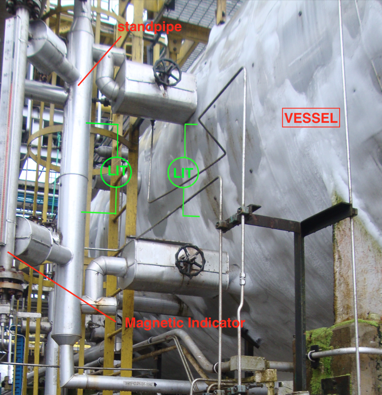
- Control Level transmitter connected directly to the vessel.
- Safety Level transmitter connected in a StandPipe (Bridle)
The superior and inferior connections of both transmitter have the same elevation, in other words, they supposed to have the same level indication.
ENGINEERING DATA:
The specification of the transmitters are:
- Dp cell Transmitter + Diaphragm seal.
- Process connection 2" FLG 600# RJT + Flushing Ring
- Capillary fluid: Syltherm XLT (0,85 SG)
- Control Transmitter: Foundation Fieldbus (Rousemount 3051CD2F22A1AS2M5B4E2Q4 + 199DAB59 AFCWG4DAA9H)
- Safety Transmitter: Conventional 4-20mA (3051CD2A22A1AS2M5B4E2Q4 + 1199DAB59 AFCWG4DAA9H)
Our vessel (vapor-liquid separator vessel) receive a stream of Natural Gas (GAS IN) and operates with 3 phases:
- Gás (lighter Hydrocarbon components). - GAS OUT
- Liquid HC (Heavier Hydrocarbon components). - OIL OUT
- Glycol + Water - WATER OUT
Vessel operation conditions:
- Pressure: 39,5 kgf/cm2G
- Temperature: -28 Celsius Degrees (Below zero temperature).
- Gas Density: 43,31 kg/m3
- Liquid HC Density: 530,00 kg/m3
- Glycol+Water Density: 1074,2 kg/m3
Boths instruments are installed to measure the LIQUID HC phase (SG 0,53).
- Distance between Superior and Inferior Level Connections: 1000mm
Range: -850mmh20 to -320mmh20. (0% and 100% - without gas weight compensation)
The vessel and the standpipe have insulation.
MEASUREMENT PROBLEM:
Although the transmitters are equal and have the same elevation in their process connection, they present different percentage level indication:
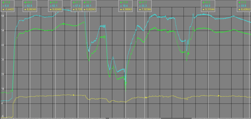
The instrument that is connected to the standpipe (Control - Green Line ) always show its indication below the instrument that is connected directly to the vessel (Safety - Blue line ).
MY HYPOTHESIS:
1) Calibration mistake
Once they have a different system (Foundation Fieldbus and 4-20mA) maybe occurred any mistake in calibration process (range selection and parametrization).
I saw the configuration and both have the same calibrated range (-850mmH20 to -320mmH20).
Any of you can see any calibration mistake can cause this kind of error between this transmitters?
Can some AI block parameter cause this difference?
2) Measurement Difference Cause by Process (StandPipe x Vessel)
After I went to the field I started to think that this error could be caused by a Convection Flow between the standpipe and the vessel.
If the standpipe has a higher temperature, can it cause the difference between the transmitters?
As they are DP transmitters, I think just density variation (static analysis) does not explain the difference between them, once they are calibrated with same range.
Is the vessel work in a thermodynamic equilibrium?
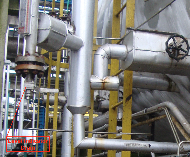
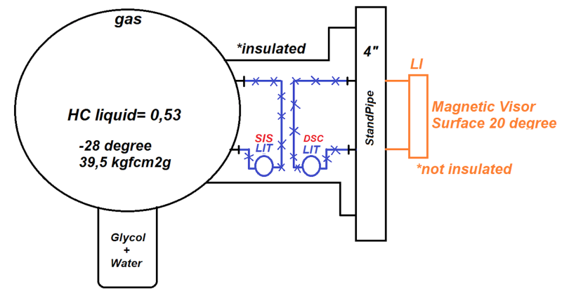
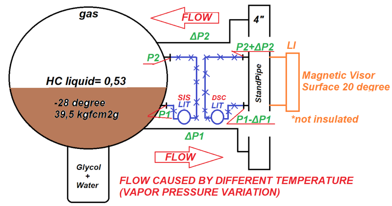
The Standpipe has a Magnetic indicator (304L body - not insulated) and seemed to be at a hotter temperature than the vessel. I used a pyrometer and the temperature of the Magnetic Indicator surface was 20 Celsius Degrees (positive and have way more temperature than -28 degrees of the vessel).
Once the magnetic indicator is not insulated, Could it induce error caused by excessive heat transfer? Can it make the temperature in standpipe hotter than the vessel?
Can the evaporation in the standpipe be causing a flow due to the convection phenomenon?
If yes, I think it causes a different pressure in both transmitters. See figure below.
Thank you very much for your attention.
If you need any more information, please ph.prado@gmail.com or SKYPE: pedrohenriquesousaprado
I have some prints of the configuration.
Best Regards,
Pedro H. S. Prado
I am having problems with level measurement in a vessel.
In this vessel, we have 2 level transmitters (one for safety and one for control) and both are DP transmitter with diaphragm seal.
Those transmitters are connected in different process connection, being them:
- Control Level transmitter connected directly to the vessel.
- Safety Level transmitter connected in a StandPipe (Bridle)
The superior and inferior connections of both transmitter have the same elevation, in other words, they supposed to have the same level indication.
ENGINEERING DATA:
The specification of the transmitters are:
- Dp cell Transmitter + Diaphragm seal.
- Process connection 2" FLG 600# RJT + Flushing Ring
- Capillary fluid: Syltherm XLT (0,85 SG)
- Control Transmitter: Foundation Fieldbus (Rousemount 3051CD2F22A1AS2M5B4E2Q4 + 199DAB59 AFCWG4DAA9H)
- Safety Transmitter: Conventional 4-20mA (3051CD2A22A1AS2M5B4E2Q4 + 1199DAB59 AFCWG4DAA9H)
Our vessel (vapor-liquid separator vessel) receive a stream of Natural Gas (GAS IN) and operates with 3 phases:
- Gás (lighter Hydrocarbon components). - GAS OUT
- Liquid HC (Heavier Hydrocarbon components). - OIL OUT
- Glycol + Water - WATER OUT
Vessel operation conditions:
- Pressure: 39,5 kgf/cm2G
- Temperature: -28 Celsius Degrees (Below zero temperature).
- Gas Density: 43,31 kg/m3
- Liquid HC Density: 530,00 kg/m3
- Glycol+Water Density: 1074,2 kg/m3
Boths instruments are installed to measure the LIQUID HC phase (SG 0,53).
- Distance between Superior and Inferior Level Connections: 1000mm
Range: -850mmh20 to -320mmh20. (0% and 100% - without gas weight compensation)
The vessel and the standpipe have insulation.
MEASUREMENT PROBLEM:
Although the transmitters are equal and have the same elevation in their process connection, they present different percentage level indication:
The instrument that is connected to the standpipe (Control - Green Line ) always show its indication below the instrument that is connected directly to the vessel (Safety - Blue line ).
MY HYPOTHESIS:
1) Calibration mistake
Once they have a different system (Foundation Fieldbus and 4-20mA) maybe occurred any mistake in calibration process (range selection and parametrization).
I saw the configuration and both have the same calibrated range (-850mmH20 to -320mmH20).
Any of you can see any calibration mistake can cause this kind of error between this transmitters?
Can some AI block parameter cause this difference?
2) Measurement Difference Cause by Process (StandPipe x Vessel)
After I went to the field I started to think that this error could be caused by a Convection Flow between the standpipe and the vessel.
If the standpipe has a higher temperature, can it cause the difference between the transmitters?
As they are DP transmitters, I think just density variation (static analysis) does not explain the difference between them, once they are calibrated with same range.
Is the vessel work in a thermodynamic equilibrium?
The Standpipe has a Magnetic indicator (304L body - not insulated) and seemed to be at a hotter temperature than the vessel. I used a pyrometer and the temperature of the Magnetic Indicator surface was 20 Celsius Degrees (positive and have way more temperature than -28 degrees of the vessel).
Once the magnetic indicator is not insulated, Could it induce error caused by excessive heat transfer? Can it make the temperature in standpipe hotter than the vessel?
Can the evaporation in the standpipe be causing a flow due to the convection phenomenon?
If yes, I think it causes a different pressure in both transmitters. See figure below.
Thank you very much for your attention.
If you need any more information, please ph.prado@gmail.com or SKYPE: pedrohenriquesousaprado
I have some prints of the configuration.
Best Regards,
Pedro H. S. Prado