Continue to Site

Eng-Tips is the largest engineering community on the Internet

Intelligent Work Forums for Engineering Professionals

  • Congratulations waross on being selected by the Eng-Tips community for having the most helpful posts in the forums last week. Way to Go!

Help meshing a complex part

Status
Not open for further replies.

ShadowWarrior

Civil/Environmental
Aug 21, 2006
171
Hi all,

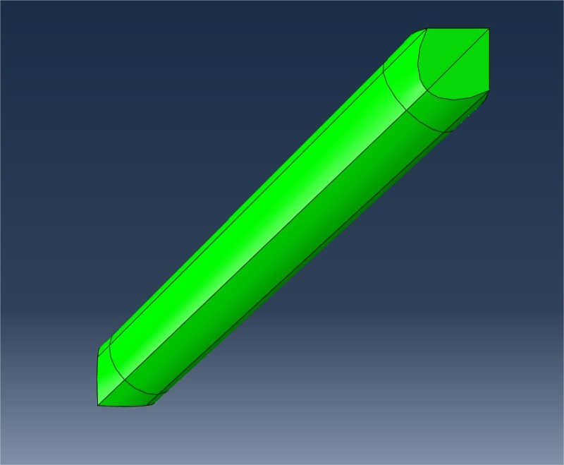
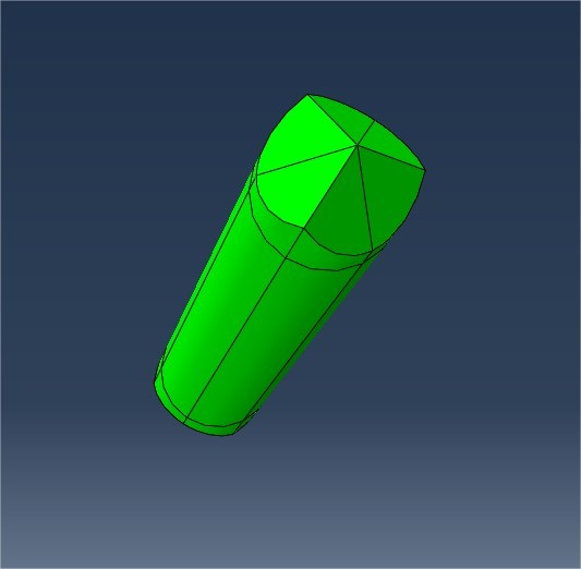
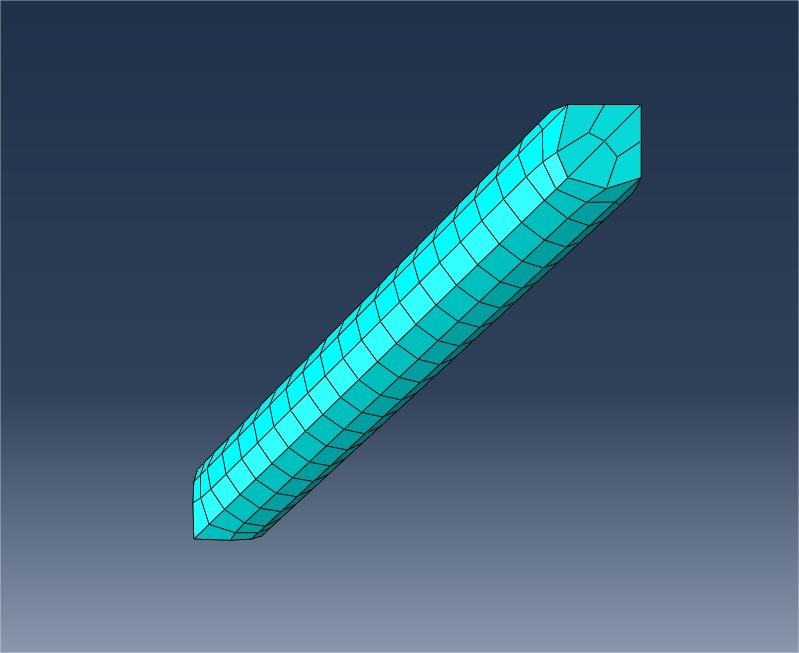
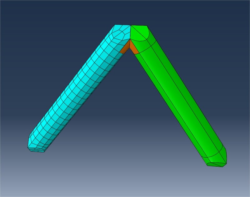
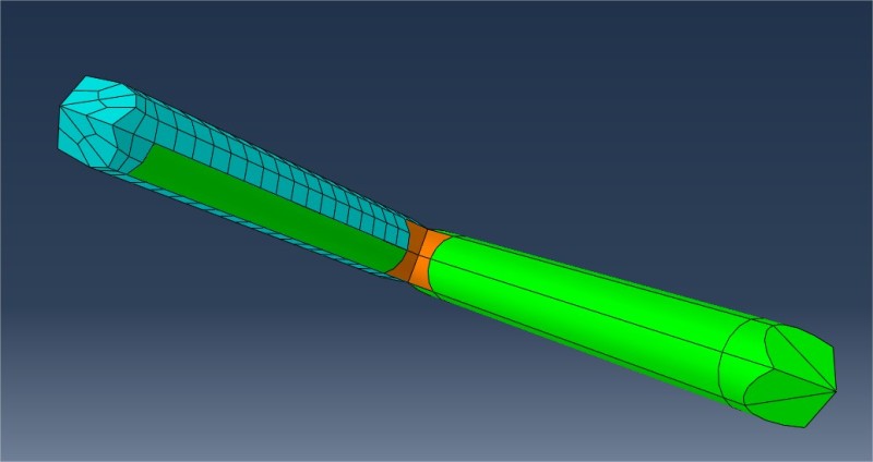
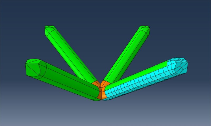
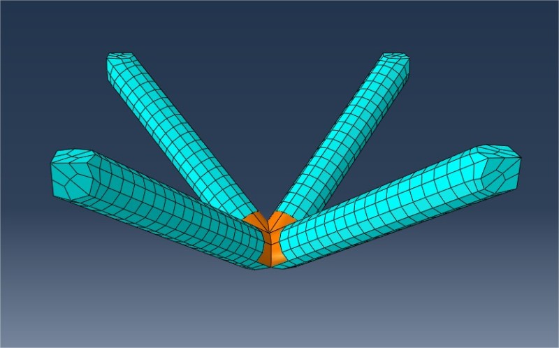
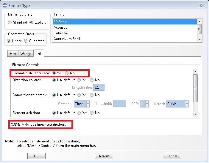
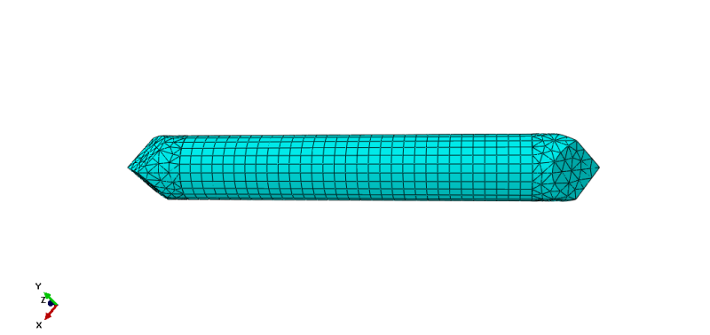
I'm meshing a lattice like solid structure but having nightmare meshing it. Would any kind hearted person have a look at it and help me mesh it? Automatic mesh is not possible, so I used Tet elements but elements are distorted. So best is to get Hex (C3D8) elements.

The cae file (Version 6.14) is here -

Thanks!
 
Replies continue below

Recommended for you

I had no problem creating a tet mesh. I used a global mesh seed of 1e-4 and the default curvature control.
 
I'm using it in a Abaqus/Explicit analysis, element size of ~1e-4 will result in huge computation time. So I need Hex element to achieve optimal performance. Can you please try to create a all Hex mesh?
 
The model can be made into structured regions by using planes to partition at existing points. The wedge shapes, however, tend to give poor hex element shapes so you're better off just using tet elements. Here's a picture of the hex meshed structure.

 
 http://files.engineering.com/getfile.aspx?folder=2d03ab65-8e19-4dbf-84e2-c706277fc7b9&file=meshproblem.png
Tet element results in weeks of computational run time (Abaqus/Explicit), Hex is absolute must. Also, Hex elements are much more robust and preferable.

Anyone? Help please!
 
Then maybe your only other option is to change your base units?

As pointed out by people above, who know what they are talking about by the way, the geometry of your structure is better suited to tets.
 
Can't you exploit symmetry? If you can not, then why not hex mesh just a replicating "unit" of the part geometry (like one rod/beam in Part module) and arrange the hex mesh in the correct pattern in the Assembly module? At worst, you have may to have move some nodes if you wish to have coincident nodes. Otherwise, a tie constraint will do the job too.

Answers to such questions will be informed by what you wish to accomplish with the model, how you are validating your model, etc.

Are you new to this forum? If so, please read these FAQ:

 
I have partitioned a single beam and it gives all Hex elements. But problem starts when I try to do it on the whole structure.


Single beam, partitioned to achieve Hex elements -
PrtScr_capture_3_wqulpq.jpg

PrtScr_capture_4_brjm2a.jpg


Single beam, meshed with Hex elements -
PrtScr_capture_5_zzi6ja.jpg


Mirrored beam, Magenta colored region is not mesh-able to achieve Hex -
PrtScr_capture_6_zapnfn.jpg

PrtScr_capture_7_ckemhi.jpg


Again, Magenta colored region is not mesh-able to achieve Hex -
PrtScr_capture_8_dlb65l.jpg

PrtScr_capture_9_jxaa1h.jpg


So guys, what is going on here? What should I do to get Hex elements on the Magenta colored region too? The new cae file is attached here -
Thanks in advance!
 
Your single beam likely doesn't have exactly the same mesh on the different sides. Try cutting the beam with more of the symmetry planes available. The length can be cut in half. I think you can also cut it along the length once or twice. I hope this helps.

Thank you.

Rob Stupplebeen
OptimalDevice.com
My Personal WP
 
You have a single part which presumably can be instanced several times and translated and rotated to make up the full assembly. If this part is a dependent part then you can mesh the individual part and hence make up the fully meshed assembly. On those faces in contact just tie the surfaces together. I'm not sure what you've done other than to possibly merge the parts together and so losing the structured region. I notice that with the hex mesh of the single part has elements that are badly distorted which will give warning messages.

 
Hi corus, Can you suggest any other option to have un-distorted elements at those regions?
 
There's not a lot you can do given the angles in the part. Refining the mesh doesn't help either though for an arc you should be looking at an element size that subtends at least 15 degrees. Your mesh looks too coarse for that criteria. Warning messages on element shape aren't necessarily a bad thing but if you want to avoid them altogether then use tet elements and pay the price for a more expensive model to run.

 
Hi corus, Its impossible to get Hexa mesh without at least 5% elements showing warning. So I used all Tets, but the Force-Displacement gives higher resisting force than it should be. I have read on Abaqus manual that C3D4 Tets are stiffer than C3D8 Hex elements. So should I use the Hex elements despite the warning messages?
 
Untitled_lxqben.jpg


This way? But it still shows the Tet element as C3D4.
 
Quadratic means C3D10M, which gives 70% elements warning!
 
I meshed the original assembly of a single part using a mesh size of 1e-4 and the mesh verification said there were no elements to produce errors or warnings. It did give 37000 elements though.
I'd try the hex elements and put up with the warning messages and check to see if your results look reasonable. You could also use a simple static test case to compare the results with a tet mesh before moving on to do the explicit analysis.

 
An alternative would be to use a mix of tet elements and brick elements. The regions that produce poor hex element shapes (mostly at the tips of the parts) could be meshed using tet elements, and the other regular regions meshed using hex elements. The connecting surfaces between tet and hex elements are automatically tied together. This gets rid of any warning messages and reduces the number of elements and nodes. The problem with this approach is you get a discontinuity in your results at the connecting surface which is ok-ish if the connecting surface is away from regions of interest.
mixedtethex_pczacd.png
 
Status
Not open for further replies.

Part and Inventory Search

Sponsor