Continue to Site

Eng-Tips is the largest engineering community on the Internet

Intelligent Work Forums for Engineering Professionals

  • Congratulations IDS on being selected by the Eng-Tips community for having the most helpful posts in the forums last week. Way to Go!

Help needed to understand this control scheme 1

Status
Not open for further replies.

MartinLe

Civil/Environmental
Oct 12, 2012
394
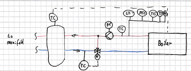
Consider this setup of a boiler:
red is hot water/flow, blue is cold/return. The boiler is non-modulating. This is an existing plant with no real documentation for the heating system. Tehre will be numerous refurbishment works, part of this is a new PLC for the heating system that I may write the narrative for.
Heatingcircuit_um93p8.png


Things I forgot in my little drawing: a TC on the suction side of the pump, position encoder on the three-way valve

1. The way I understand it is this:
If the temeprature in the return is too cold, the three-way valve will mix hot water into the return flow.
The flow through the boiler is determined by the pump & constant, so at constant power the temp. rise between return and flow will be constant. So if I keep the return temp. constant I will get my constant, desired flow temp.
The only way to implement this control scheme is a sort of table where for a range of return-temps I have a setting for the valve.

Question 1: Is my understanding correct?

2. Modulating burner
There's two of these boilers, one will be swapped for a modulating burner. The two will never be active a t the same time.
Question 2: Is there any reason to keep the three-way valve and control scheme, and not just have pump run and adjust the burner power to temp. in flow (?
 
Replies continue below

Recommended for you

1) No your understanding is off. Think about what the return TC is telling you about the system as the temperature rises and falls. Also, where is the TC relative to the 3-way valve and what will happen to TC as the 3-way valve modulates.
As TC goes down the heating coils in the system are using heat. In order to meet this heating demand the 3-way valve needs to modulate to direct HHW to the system.
As TC increases with less heating load, you want the 3-way valve to modulate to direct more HHW back to the boiler. Also as the temp. returning to the boiler gets high enough you will want the boiler to de-energize, or modulate down to save energy and maintain proper HHW supply temperature.

2) Yes you will need to keep the 3-way valve and piping setup. If you want to remove the 3-way valve you will need to modify the piping at heating coils adding 3-way valves around them. If you want to save more energy, put VFDs on the pumps. You will still need the 3-way valve so the pump can maintain a minimum flow at minimum heat demand.


Bit of as strange set-up and without seeing the rest of the system it's not easy to see how flow is modulated. Controlling on temp into the boiler would alter the temperature out on the basis that the flow is clearly verying or the heat demand is varying, but flow remains the same.

It's unclear how this system works in practice. For a non modulating boiler the only means of control is to turn the boiler on and off within certain temperature bands. If the users are using less heat than the boiler puts out then the outlet temperature will increase until it reaches a maximum. If they use more then the boiler works flat out and the temperature decreases until some sort of equilibrium is reached.

This modulating valve thing just seems to get in the way and adds complications to the system.

The only other reason is that the boiler has a min incoming temperature for perhaps condensation and that is the real control point??

normally temperature control is on the hot water outlet to keep it constant.

Remember - More details = better answers
Also: If you get a response it's polite to respond to it.
 
More things that maybe important that you won't find on my drawing:
I should have written burner, not boiler, there's no real heat water storage in the heat source
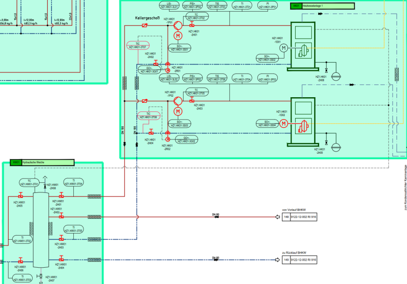
The burners are connected to the heating manifold via a hydraulic switch. As far as I can see on the P&ID, the on/off signal for the burner comes from a TC on top (warm side) of the hydraulic switch.
There's some thermal inertia in the system (large hot water tank that is heated by couild from the manifold)
All heat users have their own heating pumps anmd 3-way valves
There's other heat sources (CHP) connected to the same hydraulic switch, these have provided all the heat for the last years.

I assume the whole setup works like this as of now:
temeprature in switch falls to below some t_min, burner is switched on, temp. in switch rises to some t_max, burner is switched off.
My understanding of the current situation is of course less important than that I come up with a working narrative.

So, @dbill:
"what will happen to TC as the 3-way valve modulate"
I think nothing at first as the flow from 3-way valve to TC is burner - pump - switch - heating manifold - consumer - manifold - TC (unless there's a short circuit through the switch). the TC will react very slow to the modualting valve.
"As TC goes down the heating coils in the system are using heat. In order to meet this heating demand the 3-way valve needs to modulate to direct HHW to the system."
This would mean that less hot water is mixed into the return, so my temp. at the inlet of the burner is even lower leading to a lower flow temp ...
I think I confused you with the word boiler (sorry)? But I think my description makes more sense (though I understand that yours is more logical if the boiler where a hot water storage or similar)

@ littleinch
Why do you think flow will vary much?
the burner pump is hydraulically isolated from the heating circuit by the switch, so I'd assume what the heating pumps do on the manifold has little influence. But I need to consider if this is a safe assumption to make.

The point about min. temp to the burner for condensation etc. is duly noted.
 
The function of the boiler/burner/whatever is to supply water at some predetermined temperature. To ensure that the supply hot water is at the correct temperature, LittleInch is correct that you need/have a temperature sensor on the hot side of the boiler/burner (not shown in your diagram).

The temp sensor you have shown in your diagram controls only the 3-way valve. The purpose of this sensor and 3-way valve is to protect the pump, hot water storage tank and other equipment/users from damage. The setup you show in your diagram allows hot water from the pump to bypass the storage tank and other equipment/users and to be directed back to the boiler/burner. The reason for by-passing is simple, the hot water is not needed. This is not a strange setup as LittleInch suggested since a system with a constant flow pump requires a by-pass at some point in the system.

Keep in mind that this 3-way valve is not a "mixing valve"; it is not controlling the temperature returning to the boiler. It is controlling the amount of flow going to the storage tank and other equipment/users. The feedback from the temperature sensor (TC on your diagram) is an indicator of how much heat the system is removing from the hot water. As this temp goes down, it means the system is removing more heat from the water; to compensate for the extra heat being removed, you need to supply more hot water to the system so the 3-way valve modulates to shutoff flow through the bypass piping (shown as the pipe from the hot water side to the 3-way valve) and allow more flow from the cold water return piping.

As TC increases, it is an indicator that the system is removing less heat so the 3-way valve will modulate to allow more water through the by-pass piping and less through the system.

Since the existing system is not modulating, at some point the temperature coming from the boiler/burner will reach a maximum desired temperature which is being monitored by a sensor you have, but is not shown. When that max temperature is reached the boiler/burner will shut-off. The pump does not.

To be sure this is a very inefficient way to do things, but before VFDs and modulating boilers, that is the way it was done.
 
I will need to sleep over this.
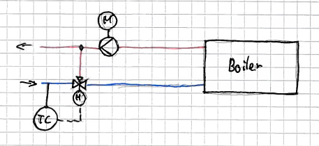
Here's an updated drawing:

Heatingcircuit_p3sord.png


My idea for when the modulating burner is installed: control burner power for temp. on flow side, uses three-way valve only to ensure a min. temp in the burner is kept. Does this make sense? Need to sleep on this too.
 
What's the age of your boiler?

From what I see, that is typical anti-corrosion setup which saves boiler from too low temperature what would cause condensation of combustion gases and eventual corrosion.

That is mandatory for all non-condensing boilers.

That is, therefore, protective, not control setup, and takes precedence over control setup which is likely linked with burner controls. Control temperature sensor is the one drawn on top of buffer tank. It swithces boiler on and off and do everything else, but return temperature sensor always take over when boiler return temp falls bellow fixed setpoint (that is mandated by boiler manufacturer). In practice, that mostly happens initially, when firing boiler, or after longer stand by.

Sensors and switches manifold you presented in second drawing resembles typical DIN hydraulic safety set, and it's also used in current EN standards.

In short, you must not change anything of that.
 
Bypass and continuous flow loops are often added for other reasons. Some residential hot water supplies have a separate pump to circulate water through the normal usage pipes and back to the water heater to "preheat" the pipes and "stage" the hot water so that you can turn on the water in the shower in the morning and get hot water much faster and with less waste than if you had to dump all the cold water between your shower head and the hot water heater; with the circulation pump, you're only dumping the cold water between the shower head and the tee directly above the shower head in the attic. In my house, that's a reduction of about 60 ft of pipe volume in wastage in the master bathroom. The last shower in the loop is almost 120 ft of pipe from the water heater.

TTFN
I can do absolutely anything. I'm an expert!
homework forum: //faq731-376 forum1529
 
First off, what do you mean by "hydraulic switch"?? To me this is a an electric switch which is controlled by hydraulic pressure - a pressure switch if you like. I have a feeling you mean something completely different, but I don't know what it is. - Heat exchanger maybe? Is that tank more like a standard indirect domestic hot water tank with a coil inside?

Drazen - I happen to agree with you, but the point remains that the TC for the return line needs to be downstream of the three way valve not upstream. Being upstream means it cannot sense when the temperature into the boiler / burner changes.

Perhaps rather than drip feeding data, you can simply attach the P & ID or relevant bits so we get a clearer picture of what is going on.

Remember - More details = better answers
Also: If you get a response it's polite to respond to it.
 
LittleInch, you are right, I did not pay attention to it at all.

Historically, some three way cocks were used that had only few mixing positions instead of continuous mixing, so there might be some quite brainless customary tradition behind that. Before, bypass pumps were customary instead of mixing valves, they had on/off switching and fixed flow and were used for ages for this purpose. Other than that, I cannot find any reasonable explanation why the sensor would be positioned upstream.
 
The hydraulic switch is of course a hydraulic separator (google translate failed me):
Drazen:
Boilers are about 15 years old and have hardly been in use.
3-way cock with limited positions seems likels as the position sensor is designated +-

I understand your frustration about the drip feeding of data, but please understand that I wont put the whole P&ID online.
heatingcircuit2_pjhjwp.png


Left of hydraulic separator is the manifold, the additional flow/return lines into the separator are from the CHPs.

Irregardless what is installed now, both burners will get new pumps (wilo pumps, internally controlled for head) and new 3-way valves that can be set continuosly.

One burner will be modulating (sewage gas), the other only on-off (natural gas). Only one will be active at the same time.
So I'm thinking:
check burner documentaiotn for min. return temp.

Both burners: use 3-way valves to ensure min. return temp into burner - have the valve default to say 50/50 and gradually close (less flow into return) when the TC reports hot enough return.

Modulating burner: pump runs at constant head, control burner power for flow. temp
Non-modulating burner: turn on as needed (that's a chapter on it's own as they want to save natural gas, but something we figured out), use TC in flow from this burner as an upper level switch

Thoughts?
 
all you mentioned is just half-job.

there are many checks to be done by hvac engineer before burning money. for instance, boiler documentation has to be consulted. i am pretty sure that return temp sensor positions has to be changed. both pump and three-way valve has to be set according to boiler minimum flow requirement.

variable speed pump can got into conflict with three-way valve anyhow. why they are modulating sewage gas if wanting to save on natural gas? and so on.
 
Status
Not open for further replies.

Part and Inventory Search

Sponsor