Chase123456
Aerospace
- Mar 9, 2025
- 1
Hi,
I have a screw preload problem during assembly on one of the products at my workplace.
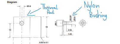
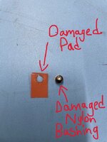
Basically, production workers have been applying a set torque of 0.82 Nm (which is a typical M3 torque for our products) and realising that this value of torque causes damage to the thermal pad (made from rubber insulated electrical fiberglass) and the nylon bushing.
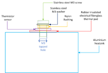
This isn't a typical preload problem as there a few things being sandwiched between the screw when torqued.
My question is:
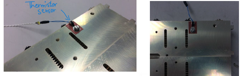
How can i determine a lower torque value which will be suitable to ensure good thread engagement and contact between the thermal pad and thermistor sensor but also ensure that the pad doesn't become damaged.
Can someone guide me on how i could determine this?. I know it'll probably involve calculating the compressive stresses due to the axial loading but i'd greatly appreciate if someone could help out with a worked example and the final torque value.
My assumption is that the critical weak point in this arrangement is the nylon bushing which deforms and then damages the insulator pad.
Please see attached schematic to help visualise this as well as drawings for the parts and damage seen during assembly.
Help would be highly appreciated. Thanks.
I have a screw preload problem during assembly on one of the products at my workplace.
Basically, production workers have been applying a set torque of 0.82 Nm (which is a typical M3 torque for our products) and realising that this value of torque causes damage to the thermal pad (made from rubber insulated electrical fiberglass) and the nylon bushing.
This isn't a typical preload problem as there a few things being sandwiched between the screw when torqued.
My question is:
How can i determine a lower torque value which will be suitable to ensure good thread engagement and contact between the thermal pad and thermistor sensor but also ensure that the pad doesn't become damaged.
Can someone guide me on how i could determine this?. I know it'll probably involve calculating the compressive stresses due to the axial loading but i'd greatly appreciate if someone could help out with a worked example and the final torque value.
My assumption is that the critical weak point in this arrangement is the nylon bushing which deforms and then damages the insulator pad.
Please see attached schematic to help visualise this as well as drawings for the parts and damage seen during assembly.
Help would be highly appreciated. Thanks.