Continue to Site

Eng-Tips is the largest engineering community on the Internet

Intelligent Work Forums for Engineering Professionals

  • Congratulations IDS on being selected by the Eng-Tips community for having the most helpful posts in the forums last week. Way to Go!

Help with basic question about Capacitor Banks in 3-Phase Systems

Status
Not open for further replies.

Wfg42438

Electrical
Apr 10, 2017
70
Hello,

I have the following question regarding a capacitor bank.

I can't seem to visualize how a capacitor bank is connected to a 3Phase system.

Now capacitor banks are made for various kVar ratings and applications so lets focus on one example.

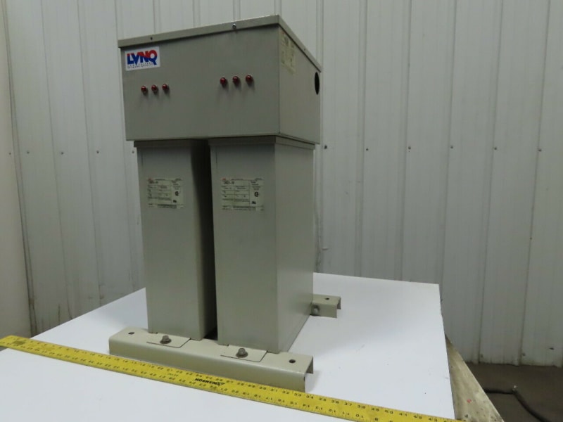
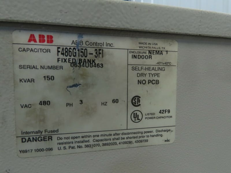
In the sample below we have a 480 V, 3Ph, 150 kVar capacitor bank.

Now, this bank is made up of two individual capacitor enclosures which are rated each at 75 kVar.

What I am trying to understand is which of the following scenarios is true:

1. In this structure since there are two units injecting 75 kVar each does this mean each enclosre houses a single 3Phase capacitor rated at 75 kVar?

or

2. Does each structure contain several capacitors that are configured to deliver a total of 75 kVar as assembled?
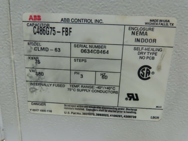
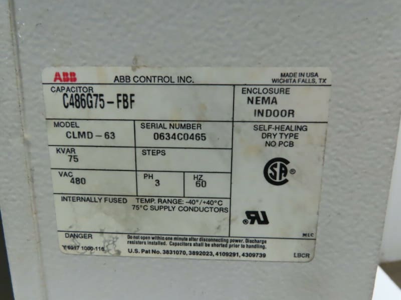
ABB_Dual_1_fq6vb7.jpg

ABB_Dual_2_t9fhib.jpg

ABB_Dual_3_ywhscw.jpg

ABB_Dual_4_njurze.jpg


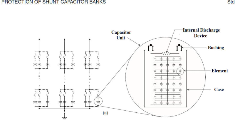
Lastly when IEEE-C37.99 refers to a capacitor unit in the image below:

In regards to the sample bank provided what is the capacitor unit they are referring to?
Would that mean the individual 75 kVar units are connected per phase or is that not a correct interpretation?
Comparison_luphpk.jpg
 
Replies continue below

Recommended for you

Dear MR.Wfg42438

"... we have a 480 V, 3Ph, 150 kVar capacitor bank....is made up of two individual capacitor enclosures which are rated each at 75 kVar ..."
which of the following scenarios is true:
Q1. In this structure since there are two units injecting 75 kVar each does this mean each enclosure houses a single 3Phase capacitor rated at 75 kVar?
A1. No. Usually each enclosure may contain numerous " basic capacitor element*", they add up to 75kVAr; see answer A2 for detail. These two individual banks each rated [75 kVAr] are [connected in parallel to attain [150 kVAr ]. You may be able to see the 3 wires connecting terminal A1 to A2, B1 to B2 and C1 to C2 of bank 1 to bank 2. Your connection to the load (150 kVAr ) may be connected to e.g bank 1 terminals A1, B1 and C1. Attention: Do NOT remove the [paralleling) wires.
Q2. Does each structure contain several capacitors that are configured to deliver a total of 75 kVar as assembled?
A2. Yes. Usually each structure contains several basic capacitor element* that are configured to deliver a total of 75 kVar as assembled. Usually they have a [limited] number of "basic capacitor element*" with different capacities and rated voltage. They parallel the [basic elements*] to attain the [capacity] or in series to attain the [rated voltage]. Each structure usually contains several basic capacitor elements* in it.
Che Kuan Yau (Singapore)

 
@Che12345

Thank you so much for your answers on these topics. I now have a clear picture that capacitor banks are typically made up of multiple basic capacitor units (or cans) to deliver the rated kvar rating.


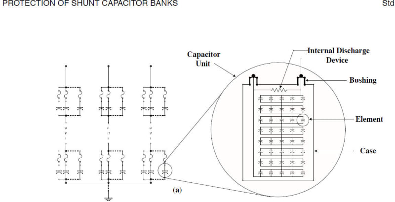
Lastly I wanted to ask about a sample image in IEEE-C37.99 which refers to a "capacitor unit" in the image below:

With respect to the 150 kvar sample bank you reviewed earlier what part of the capacitor bank is the "capacitor unit" in the image from the standard refer to?

Based on what they are showing I am not clear if each 75 kVar enclosure represents a "capacitor unit"

If this is the case does that mean the each 75kVar unit is connected per phase since they they show a single "capacitor unit" per phase or is that not a correct interpretation?
Comparison_2_jkz0qd.jpg
 
Dear Mr. Wfg42438

Q1. " ... a sample image in IEEE-C37.99 which refers to a "capacitor unit" in the image below:
With respect to the 150 kvar sample bank you reviewed earlier what part of the capacitor bank is the "capacitor unit" in the image from the standard refer to? "
A1. The LHS drawing (a) is correct, showing a 3ph bank internally connected in Y formation. Each branch may comprising of numerous " group " [each group may comprising of 3 or more " capacitor unit" connected in parallel]. Each " capacitor unit" is further broken down with greater detail shown in RSH drawing. There may be numerous " group " connected in series.

Q2. "...Based on what they are showing I am not clear if each 75 kVar enclosure represents a "capacitor unit. If this is the case does that mean the each 75kVar unit is connected per phase since they they show a single "capacitor unit". per phase or is that not a correct interpretation? ..."
A2. The RHS drawing is correct, showing detail of a " capacitor unit" . In this drawing, it shows
a " capacitor unit" comprising of 8 " group " , each " group " comprising of 5 [" basic elements"]. Total of 8 [" group "] are connected in series.
Che Kuan Yau (Singapore)
 
My apologies I am still not clear how I can relate this sample from the capacitor units to the sample equipment made up of two 75 kVar enclosures.

Can you confirm if each 75kVar unit represents what its referred to in the standard as a capacitor unit?

If this is the case does that mean each 75kVar unit represents one of the capacitor units shown in parallel per phase?

Also would that mean that in that sample y connection you would have a 75 kVar unit per phase?
 
Yes, each 75kVAR box is a capacitor unit, the part inside the circle from the standard drawing.

The capacitor units you have are 3-phase, not single phase as shown in the standard drawing.
 
@lionelHutz

I see thank you for clarifying so in my sample set up each 75 kVar enclosure is a capacitor unit and both of these units combined is what is typically referred to as a capacitor bank.

So in the standard drawing, the assumption is each capacitor unit is a single-phase element which is why we see one capacitor unit per phase.

Since the sample I provided is a 3Phase element this means the two 75 kVar units are wired together and then out of the bank come out three leads connecting to the separate phases of the three-phase system.

In other words since its three-phase bank, we dont place each capacitor unit per phase.

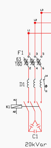
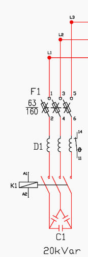
In reality, this bank is connected together to deliver 150 kVar into the three-phase system directly something like the image below.

Where the connection diagram shown below say "20 kVar" (sampled from it would really be two sets of capacitors connected to the three-phase system delivering 75 kVar each

Sample_Connection_sxhvo2.jpg
 
Dear Mr. Wfg42438 (Electrical)(OP)24 Aug 20 15:16
Q1. ".. not clear ... from the capacitor units to the sample equipment made up of two 75 kVar enclosures. Can you confirm if each 75kVar unit represents what its referred to in the standard as a capacitor unit? "
A1. No. A 3ph bank with name-plate rated e.g. 75 kva, it is the "consolidated" [total 3ph va] of the whole bank. It is irrespective of whether internal connection is in Y or D, number of "groups" or number of "capacitor units" . It is NOT the value of each " capacitor unit", inside it.

Q2. "...If this is the case does that mean each 75kVar unit represents one of the capacitor units shown in parallel per phase?"
A2. No. The rating on the name-plate of a 3ph bank e.g.75 kva is NOT the value of each "capacitor unit" . It is the total value of the 3ph bank. Each 3ph bank may comprising of numerous "groups" and "capacitor units" connected in Y or D; to form into a (single) [3ph bank] of 75kva.

Q3. "... would that mean that in that sample y connection you would have a 75 kVar unit per phase?
A3. No. The rating on a 3ph bank e.g 75kva is the total value of the 3ph bank. It is NOT the value in one of the Y or D phases.
Che Kuan Yau (Singapore)
 
Dear Mr. Wfg42438 (Electrical)(OP)24 Aug 20 16:32

Q1. "... so sample set up each 75 kVar enclosure is a capacitor unit and both of these units combined is what is typically referred to as a capacitor bank.
A1. No. The e.g. a 3ph 75kva bank is NOT the value of a 'capacitor unit". A 3ph 75kva capacitor can be a stand-alone "bank" by itself, in a metallic [enclosure or tank]; with three terminals for external connection. There are numerous "standard" stand-alone "banks" of various 3ph ratings
e.g. 25kva, 50kva, 75kva...To attain a 3ph e.g. 125kva may have three banks [2 x 50kva + 1 x 25kva] connected in parallel.Each bank is by itself, in a metallic [enclosure or tank].

Q2. " ... the standard drawing, the assumption is each capacitor unit is a single-phase element which is why we see one capacitor unit per phase".
Q2.1 Yes. each " capacitor unit" is a single-phase element.
Q2.2 In a Y or D 3ph formation, the capacitance in [each phase] is represented by an "equivalent C" for simplicity. Attention: the "equivalent C" is NOT the [3ph kva rating], on the name-plate.

Q3. Since the sample ... is a 3Phase element, this means the two 75 kVar units are wired together and then out of the bank come out three leads connecting to the separate phases of the three-phase system."
A3. Yes. Each enclosure/tank is a stand-alone 3ph rated 75 kva. Connect two in parallel to form a 150kva "combined" bank, comprising of two enclosures/tanks.

Q4. In other words since its three-phase bank, we dont place each capacitor unit per phase.
A4. Yes.

Q5. In reality, this bank is connected together to deliver 150 kVar into the three-phase system directly something like the image below.
A5. Use two 3ph banks each rated 75kva, connect them in parallel. It is also possible by using two 3ph banks [100kva + 50kva] = 150kva , in parallel; or any other combination from the "standard" bank available.
Che Kuan Yau (Singapore)


Each 75kVAR box from your pictures is a capacitor unit following the terminology used in IEEE-C37.99.

The 75kVAR box contains a number of capacitor elements to build it.
 
@lionelhutz
If I’m not mistaken the only difference between my example and the IEEE-C37.99 “capacitor unit” is that in there description each capacitor unit is 1phase.

In my case each capacitor unit is 3phase so each unit would not be placed per phase.

Instead each unit would interface the system similar to this image
8786C460-0B48-4185-A826-6FB0DE9824E0_nod6qy.jpg
 
Dear Mr. Wfg42438 (Electrical)(OP)25 Aug 20 19:28
@lionelhutz
Q1. If I’m not mistaken the only difference between my example and the IEEE-C37.99 “capacitor unit” is that in there description each capacitor unit is 1phase.
A1. The "capacitor unit " shown in the LHS drawing (a) is a typical [1ph unit] with [two terminals/wires]. It is MOT a 3ph 75kva bank (which is a 3ph stand-alone bank in a metallic enclosure/tank shown. A 3ph bank [shall] be with three terminals, NOT [two].
Q2. In my case each capacitor unit is 3phase so each unit would not be placed per phase.
A2. No. Each "capacitor unit" shown in the drawing is a 1ph unit. For you 3ph system, you do NOT have to care about the quantity and the va rating of each "capacitor unit" in the enclosure/tank. If your 3ph system requires 3ph 150kva, you may order a 3ph 150kva bank in one stand-alone bank/enclosure/tank (if available); or two stand-aloe banks/tanks each 3ph 75kva connect them in parallel, or any number of banks/tanks in parallel to total 3ph kva rating as required. Attention The kva rating shown on a 3ph bank/tank (which shall be with three terminals) is the total 3ph kva/b] rating.
Q3. Instead each unit would interface the system similar to this image.
A3. If your 3ph system requires 3ph 150kva, order two numbers of each 3ph 75kva and connect them in parallel. Treat these two paralleled banks/tanks as one 150kva bank (even though they are in two separate stand-alone enclosure/tank. Attention: the fuse shall be sized for 150kva rating. When the fuse blows, [two] banks go off. You may use two each 3ph 75kva stand-alone banks, each fused based on 75kva. Advantage, when one fuse blows only one 75kva bank goes off. Attention: in this case, these two banks are NOT connected in [parallel]. BTW You may replace the fuse with MCCB, to avoid single-phasing.
Che Kuan Yau (Singapore)
 
Yes, you could connect the capacitors with a power circuit like that.

Your picture shows what appears to be blown fuse indicators so I would expect there to be individual fuses on each capacitor unit. Generally, you will find 3-phase capacitors configured into a bank with fuses on each capacitor unit.

 
Status
Not open for further replies.

Part and Inventory Search

Sponsor