Hey thanks I appreciate any (especially Honest) info.
Just to clear something up, my goal is not a perpetual motion device.
I have a comprehension difficulty when I read things. I’ve read a lot and watched a lot about coils and magnets, but the concept of electrons being charged and “pushed” through copper wire in a direction and “speed” Determined by the ratio/size of magnets to coil.
Also not very good at explaining this concept because of lack in terminology on my part..
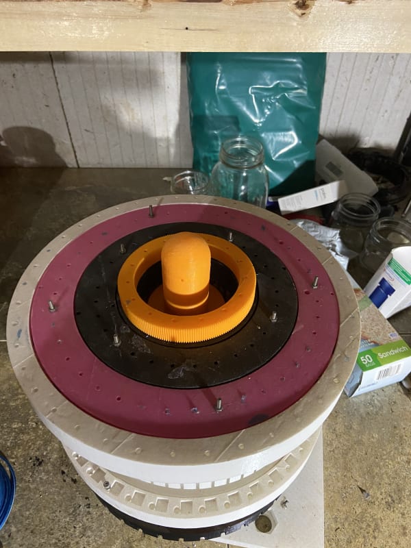
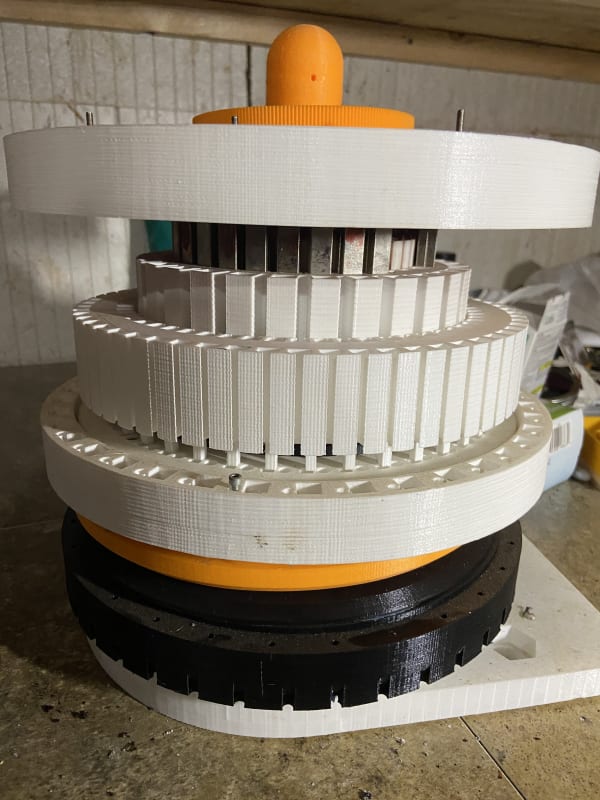
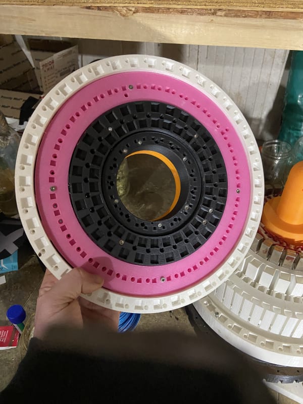
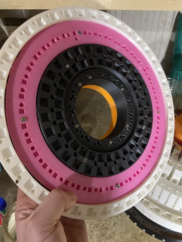
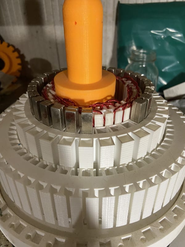
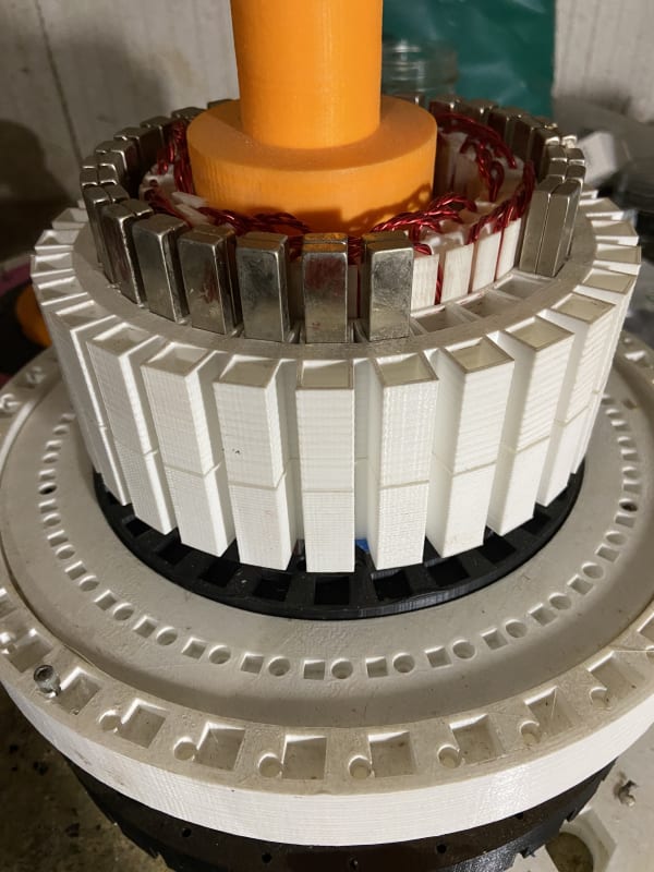
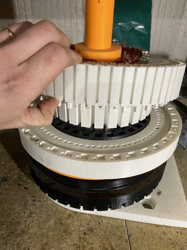
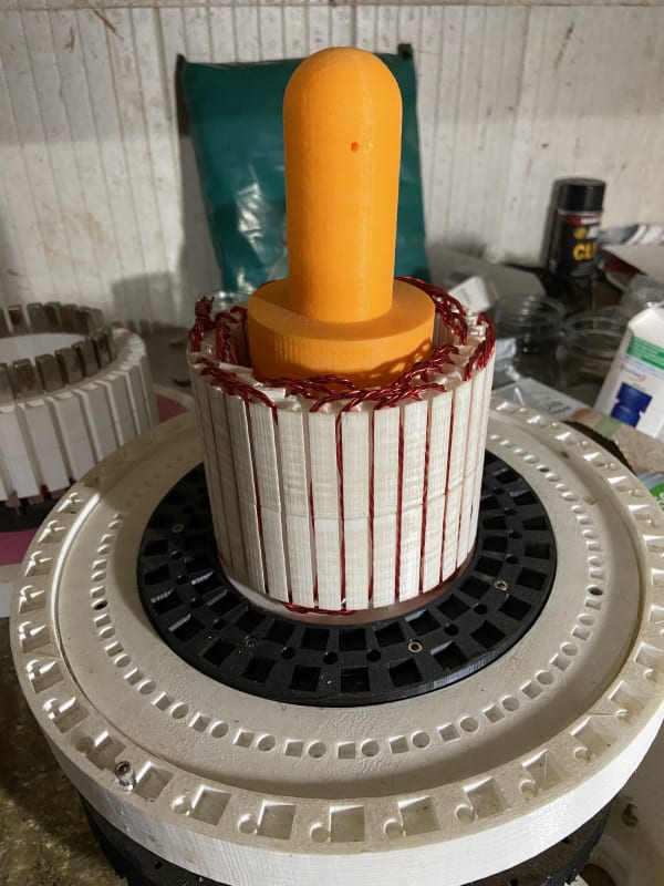
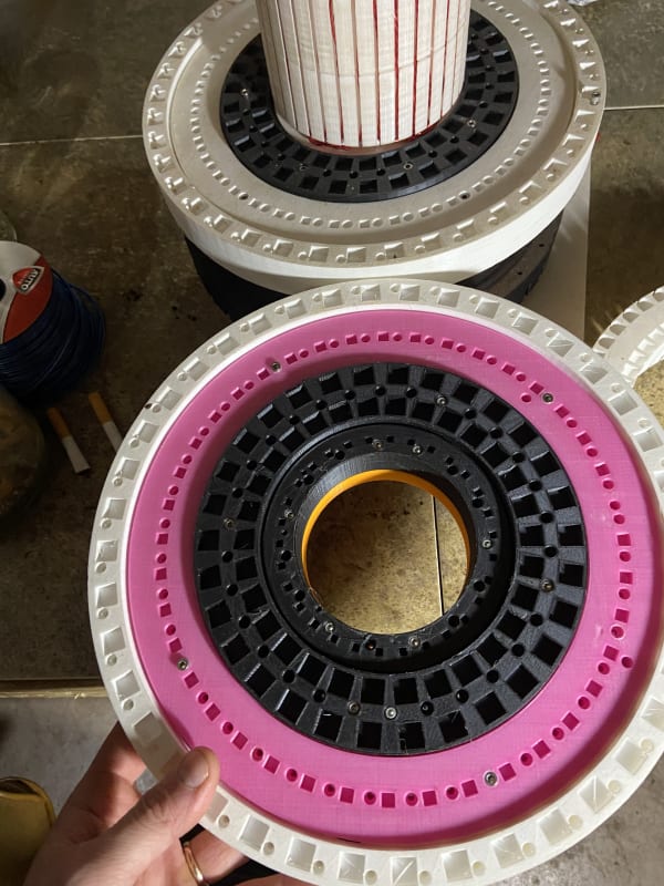
The bearing in the photo I sent has 4 separate races:
starting with smallest bearing, has 3 phase coil
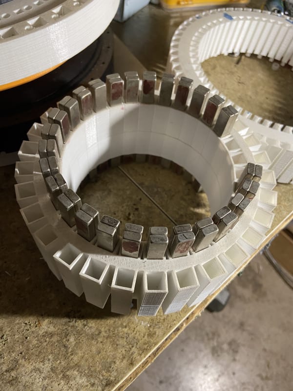
Next is the inner magnet harness which consist of two rows of magnets
3rd has the large coil in which only half is printed and shown in the photos.. the one half on the coil took 74 hours to print at .1mm with a .2mm nozzle.
The last bearing run holds the outer magnet harness these are cross roller slew bearings, they will move counter of each other driven by a planetary gear assembly.(only one of those gears in picture in orange on the inner most bearing)
I stopped printing things because I need to understand how magnetic fields react with electrons. I’m reaching out after a lot of trial and error. looking for someone to explain in a simple way, and it’s going to take kore than one example, just a heads up... if you want to help thanks, if not no worries.
There is probably 60% of the generator in the photos. It is fully designed on fusion 360. But I need my better computer to make modifications, and took a long break from this project for other projects.
If you have fusion 360 I believe I can share the design with whoever. This is just a design that came to my mind and wouldn’t leave me alone so I spent a very long time watching and reading just to learn how to use fusion 360. Got a cheap clone FDM printer and just started. Have been Learning but my brother suggested reaching out online and I’m anti social, except when I’m medicating, so here I am... But hey to each their own.
Again thanks for the help and thanks for the compliment.