Eng-Tips is the largest engineering community on the Internet

Intelligent Work Forums for Engineering Professionals

  • Congratulations waross on being selected by the Eng-Tips community for having the most helpful posts in the forums last week. Way to Go!

Help with Fence and Gate Grounding Layout

Status
Not open for further replies.

mbk2k3

Electrical
Nov 18, 2010
97
CA
I've gone through IEEE 80, local code requirements and design guidelines, but I'm struggling with the implementation of ground loops around a substation fence that has a host of interferences, different surface materials, etc.

I'm attaching a photo of the fence in question. The fence in question is the one that runs top-to-bottom in the picture.

I need ground loops both on the inside and outside of the fence.

What is throwing me off are the following:
1) Near the green building, one side of the fence is a concrete pad, the other side is grass/top soil. Do I just sawcut on the concrete side? Or use a metal grate bonded to the ground loop? Its not practical to tear everything up.
2) On the opposite side of the gate, one side of the fence is asphalt and the other side is grass/top soil. Again, do I just sawcut in the asphalt? Its not practical to tear everything up.
3) There are buried services around this gate: security cabling to card reader, power cable to gate operator, other 120V cables going to lightfixtures, and they all run around the sliding gate.
4) The gate is a sliding gate. I assume it needs a flexible ground connection as well. Any vendor/part recommendations?
5) What do I do with a ground conductor when it hits a curb?

I am all out of ideas and need practical tips on the constructability of ground loops in this area. How do I install the ground conductors? Just sawcut the concrete? Sawcut the asphalt? We can't tear the ground up because of (1) existing services and (2) highly trafficked area. We also can't change the top surface material easily.

Brownfield jobs are the worst.
 
 https://files.engineering.com/getfile.aspx?folder=40b4507a-d0c2-492c-b541-479193961bf8&file=Fence_Grounding_Question.jpg
Replies continue below

Recommended for you

mbk2k3,
1)Is the fence bonded to your substation ground grid?
2)Have you done a ground grid study and found that during a Ph-G fault inside the substation
area,the GPR is transferred as a transferred potential to the fence, and as a result if a person
is touching the fence while standing on the grass area, he is subjected to greater than your
calculated tolerable touch & step voltages?
ASPHALT is having a very high resistivity, therefore an asphalt layer will reduce the touch/step
potentials if one touches the fence while standing on the asphalt layer.Similar with concrete layer.
Additionally if the concrete has reinforced bars then the surface is an equipotential surface where
there cannot be any difference in potentials.The gate has to be bonded to the fence using flex bonds.
 
@kiribanda, yes all the grounding studies have been completed. The GPR / step / touch potentials are all within tolerable limits (as per our local requirements), but the fence still has to be bonded/connected to the ground grid.
Majority of the ground grid is not shown in the photo, and the majority of the grid is installed in native soil, with appropriate top layers.
Yes, the fence is bonded to the substation ground grid, as per the requirements of our local code.

With regards to your comment about concrete/asphalt: does that mean I don't need a ground conductor loop wherever I have concrete/asphalt?

I'm getting mixed results when I try to look up concrete being a conductor/insulator.... how do i get a definitive answer on this?
 
Not sure if we can help without known the system parameter and if any grounding calc or test been performed. Main parameters such as design LGF current, grounding/earthing topology, soil resistivity, protective device clearing time, etc are required to be known.

In Liu of calculation, a grounding/earthing test by trained and qualified personnel may be acceptable.

In the absence of any field data, the following generic suggestions are offered:
[sub]1) In the grassy area, a perimeter conductor 3 ft (1m) inside and beyond the fence is often used in HV facilities to mitigate any hazard step and touch potential.
2) Analyze if a crushed rock surface (4" to 6" thick)is necessary for the grassy area to increase the allowable potentials.
4) All the metallic parts above grade such as card reader, speed sign, security building, fence, and the gate should be grounded and connected to the main grid.
5) Use a flex conductor for the sliding gate. (Some design spec. approved coiled traveling grounding conductor).
6)In the concrete slab (<100 Ω.m), check if there is rebar that can be grounded and use as an equipotential surface (similar to an Ufer ground). In the asphalt area (10,000 Ω.m wet) the allowable step and touch potential are fairly high compared with the native soil. Depending upon the system grounding parameters and calc, there is a possibility that the area is safe without doing major digging & cuts in the area.
7) Calculations model and/or actual grounding tests are highly recommended.[/sub]


If the step and touch potential are met in the native soil, there is no much concern with the asphalt area and even the concrete slab. Double-check if the concrete has rebar. Both surfaces can be modeled and can confirm if there is an issue particularly with the touch potential.
 
mbk2k3,
You have mentioned that GPR/STEP & TOUCH potentials are within the calculated
allowable limits.
1)So why are you hesitant to bond the fence to the grid?
2)Is the fence within the substation grid?
2)If not, then how far is the fence from the grid?


its so difficult to explain without seeing the final expected layout.
see attached.
i've highlighted the fence in question, and also indicated where major switchgear equipment is located. (i.e. there are two grids interconnected with 2x #4/0 conductors and the fence in question runs right in between them)

to answer the kiribanda's questions:
1. i'm not hesitant to bond the fence. i'm just questioning what the best practices are to bond the fence without tearing up the parking lot, concrete, asphalt and avoiding the security loop interferences.
2/3. fence cuts through the ground grid technically, see screenshot

to answer cuky2000's questions:
1. the grassy area is only on the outside of the fence, and installation of the loop there will be easy. i'm more worried about inside the fence, where its concrete.
4. i plan on connecting all metallic parts above grade to the grid, but the question remains: can i just run a bare conductor along the top of the asphalt/concrete surface to get to the metallic parts? (e.g. card reader, gate mechanism)
6. did you mean to say in asphalt areas the step/touch potentials are **low**?
7. we've done all the modelling/ground grid design (third party), and the 3rd party design firm is the one that recommends the fence needs to be grounded to the system grid. but the design firm is just that...good with software, folks that don't have a good grasp of constructibility.
 
 https://files.engineering.com/getfile.aspx?folder=51955a57-3522-43ab-9301-d05216fa14e4&file=Fence_Layout_Sketch.jpg

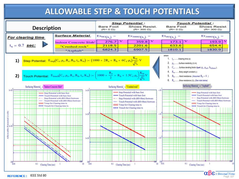
The grounding calc compares the actual voltage rise during a fault with the allowable step and touch potential which is dependent mainly on the surfacing material and the clearing time as indicated in the example shown in the figure below.

1) Asphalt (10kΩ.m) provides the highest allowable voltage in the fenced area.
2) Concrete is very tricky since varies significantly with moisture. However, its hygroscopic characteristics particularly for outdoor slabs, keep moisture from the soil helping to minimize the variability in resistivity . Most likely this site (TBD) was build with rebar. if this is confirmed, the slab can behave as an equipotential surface and minimize or eliminate the need for additional grounding loop.

SUGGESTION: Ask the engineer to run two cases:
1) CASE 1: Asphalt 10 (kΩ.m) and thickness as installed (4" ?) [sub](Expected to work without install buried conductor)[/sub]
2) CASE 2: Concrete 300 Ω.m.and consider modeling with footwear instead bare foot.
2.1 Without Rebar [sub](most likely require grounding loop)[/sub]
2.2 With Rebar [sub](most likely not require grounding loop since behave as equipotential surface.)[/sub]

>>>>>>>
Allowable_Step_Touch_Potentials_n9dblc.jpg
 
Status
Not open for further replies.

Part and Inventory Search

Sponsor

Back
Top