Eng-Tips is the largest engineering community on the Internet

Intelligent Work Forums for Engineering Professionals

  • Congratulations waross on being selected by the Tek-Tips community for having the most helpful posts in the forums last week. Way to Go!

Help with Flow Area Knockdown Factor (?) Research

Status
Not open for further replies.

Burner2k

Aerospace
Jun 13, 2015
193
0
0
IN
Hi Folks,
I am looking for some pointers on where to start my research. I am not a CFD/Aerodynamics Engineer. Currenltly providing Design/CAD support under the guidance of Aerodynamics Engineers.

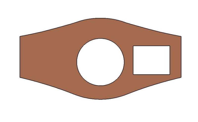
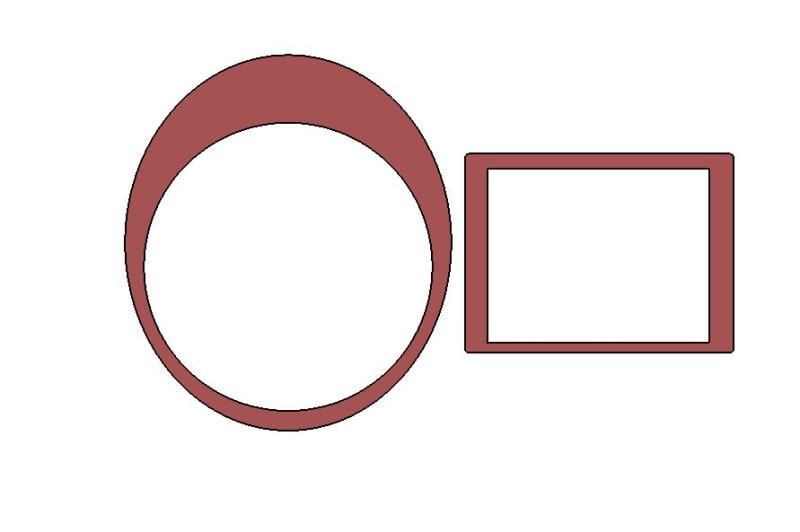
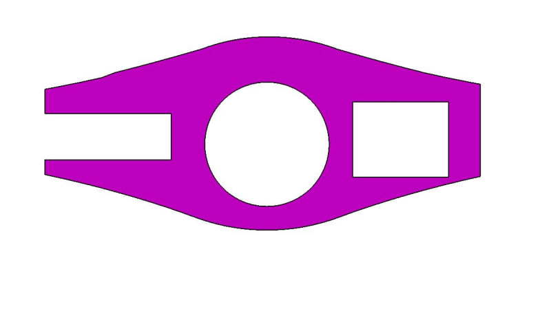
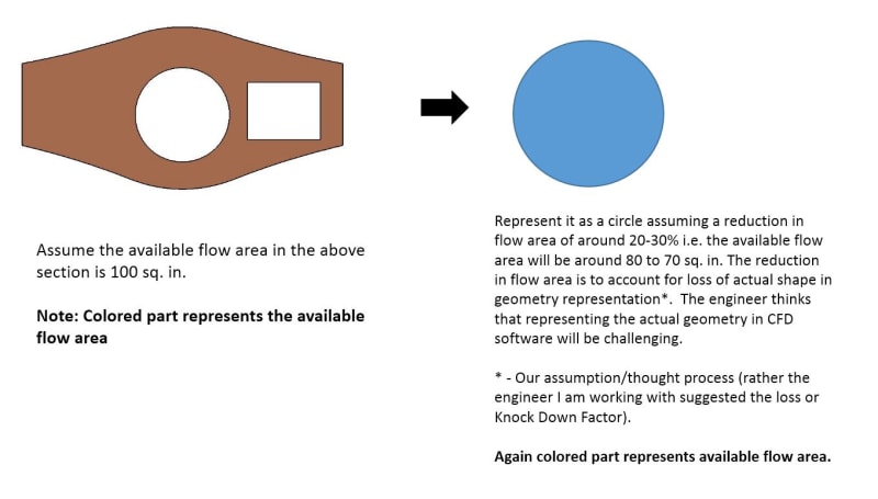
I have extracted several sections along the X-axis of a system. The sections are essentially closed contours which form areas (gaps such as cutouts etc.) where the air could flow. In other words, the area formed by these closed contours represent flow areas. The issue is that the transition in section shape is very abrupt along adjacent sections and the engineer I am working under feels that resulting surface loft (3D Surface Tube) could be too complex to be meshed within a CFD software. Instead, he suggested an idea. What if we replace the existing sections by equivalent circles. We will lost some fidelity by not including the actual shape of various sections but that could be offset by assuming some initial losses (say around 20%) in flow area. Just to give an example, if the flow area in one of the section is let's say around 100 sq. in, we could represent that section by an equivalent circle of having area of 80 sq in (assuming an initial loss of 20% in area due to not being able to capture the exact shape).

Is there any open source literature where such a task like above has been attempted? I've been asked to look around/search for the above, but tried the usual Googling with not much luck. Would appreciate any kind of pointers/support from experienced CFD/Aerodynamics folks about the above. The engineer I am working under feels more confident about the approach if we have some kind a base (such as an existing paper or guidelines) to support the above approach.
 
Replies continue below

Recommended for you

I can't comment on the approach. but I would comment on the practicality ... why design a very inefficient duct ? The duct is going to be limited by the smallest section ... why not use this section everywhere ? ok, maybe different inlet and outlet "plenums" or add profile to the inside of the ducting to remove, or at least reduce, the abrupt changes ?

another day in paradise, or is paradise one day closer ?
 
I though there was CFD software exclusively developed/refined for internal flows like this...

Regards, Wil Taylor

o Trust - But Verify!
o We believe to be true what we prefer to be true. [Unknown]
o For those who believe, no proof is required; for those who cannot believe, no proof is possible. [variation,Stuart Chase]
o Unfortunately, in science what You 'believe' is irrelevant. ["Orion", Homebuiltairplanes.com forum]
 
You're treating these cutouts like orifices, right? Discharge coefficients, etc... This was studied by NACA and NASA, back in the day. Do you have a copy of White's Fluid Dynamics textbook? I believe I saw corrections in there on that subject. IIRC "wetted area" and "effective perimeter" are the key phrases?


STF
 
Folks,
Thanks for the replies. I think I may have not stated my intention clearly in my original post. Let me try stating my issue again with help of images. Hopefully will become clear.

I have quite a few sections like these:

Section-1
Sect-1_jhzaij.jpg


Which transitions to Section-2
Sect-2_a7zmm2.jpg


and opens to a Section-3
Sect-3_whmpya.jpg


NOTE: The colored part represents the available Flow Area for Air

The idea proposed by the aerodynanmics engineer is to represent some of the sections (like Section 1 & 3) by circular areas with flow area reduction by around 20-30%. Something like this:
Image-4_khehin.jpg


The proposed idea is sort of based on his intuition along with his understanding/experience but he got no basis to go by. Thus the task to try & find an existing literature about using such an approach. At least, if we could find some material on how much reduction in area to account for based on shape, it would be an awesome starting point.

He understands the loss in fidelity of simulation due to change in geometrical shape of flow area but he strongly believes that it is an acceptable trade off.

I hope the intent is clear. Please help if possible.

Thx...
 
I just want to add that even if I am able to come up with a CAD model of a duct which will capture the different sections along the duct length, the engineer thinks it will be too complex to model in CFD & hence his suggestion of using circular flow path with reduction in area.
 
if the circle and the square are the same in each pic (they look different but that could be optical illusion), then why not use section 2 for the entire duct ?

the flow in the true duct will have such large? unintended side effects (eddies, vorticies).

I'm surprised you think CFD can't handle this, but I'm no CFD designer either.

another day in paradise, or is paradise one day closer ?
 
OK
Let's call it a manifold for lack of a better name. The excluded parts come from... somewhere... and go somewhere... How does the flow start and end in the manifold? How does the manifold divide into two separate volumes and re-combine again?
All I can say is that skin friction is likely to rule most of the flow, but the changing cross sections will also cause pressure gradients that could be drastic if the cross-section changes are also drastic. That depends on if this manifold is 10 times longer than it is wide, or 1/10 as long as it is wide.

My very first step would be to make a plot of the conduit's cross-sectional area and wetted perimeter at regular intervals through the entire path:
Like this:

X 0.00 1.00 ...
A 10.1 11.2 ...
P 12.5 13.4 ...

Use that to do a rough-pass calculation of flow velocity, Reynolds number and friction factor.
The preliminary number will be wrong, but probably be in the right order of magnitude.

The model you show approximated by a single tube isn't very realistic. A model approximated by an annular tube (circle with a circle inside it) would be better.

STF
 
RB,
You may be on to something with your suggestion i.e. try to use profile of Section-2 along the entire duct (adjusting for areas of course).

Per my engineer, the issue isn't modelling within CFD, its more of a convergence problem. He thinks representing it realistically will lead to convergence issues.

Sparweb, like RB suggested, using profile of Section-2 could be a better approach. Let me try pitching the same to fella I am working with.

Thanks again folks. Power of community thinking :)
 
Status
Not open for further replies.
Back
Top