Continue to Site

Eng-Tips is the largest engineering community on the Internet

Intelligent Work Forums for Engineering Professionals

  • Congratulations KootK on being selected by the Eng-Tips community for having the most helpful posts in the forums last week. Way to Go!

Help with motor wiring and limiting starting current 2

Status
Not open for further replies.

dvanommen

Aerospace
Jul 2, 2018
11
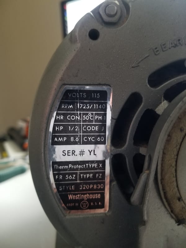
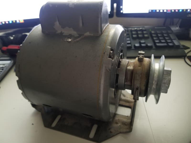
I have a Westinghouse AC motor, shown below, which I want to use to power a small bench lathe. I think the motor works fine, but I'm having two problems: correct wiring configuration and starting current.

Problem 1:
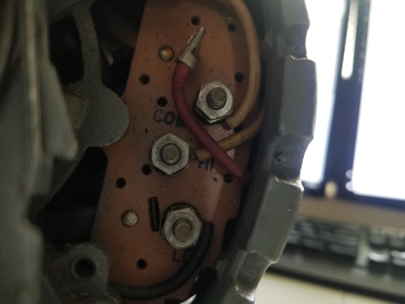
I don't have a wiring diagram for this motor. The terminals on the motor are marked COM, HI, and LOW. I'm going to wire this up with a standard 3-conductor power cable with Black, White, and Green wires. Am I correct that these should be wired as GREEN-COM; BLACK-HI; WHITE-LO? Or do I have this mixed up?

Problem 2:
I wired it up a few different ways (after it didn't work with the above order, I tried other configs) and it keeps trying to start but will trip the circuit breaker (15A) before it can get running. After a bit of research on this, I'm making an estimate that the starting current is 4x the rated running current (per the faceplate, 8.6A, so starting current is ~35A which will trip the breaker it's on). This was determined from here Link

Does anyone have any suggestions of how I can reduce the starting current of this motor? I've looked into this online as well, and there are ways to do so but all cost a few hundred dollars that I can't afford.

Thanks for your help
David
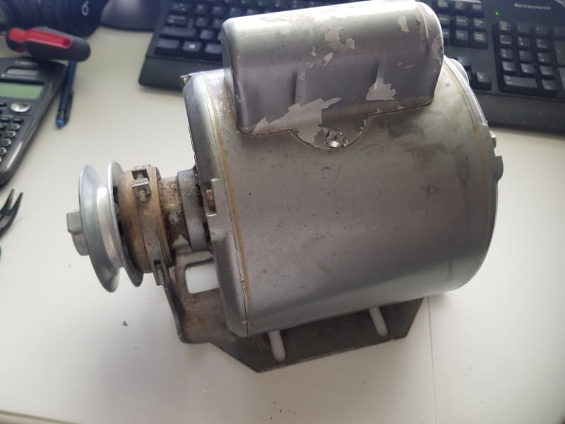
20181004_132835_cidbhe.jpg

20181004_132843_yttih3.jpg

20181004_132901_q8g531.jpg

20181004_132912_hn4rsu.jpg
 
Replies continue below

Recommended for you

Try com (N) to high (H) and be prepared to give the motor a twist the moment you plug it in.

If you need to twist it to get it started you have a starting circuit issue.

Keith Cress
kcress -
 
Well that wiring config fixed both issues. White to COM and black to HI, leaving green and LO disconnected. No need to spin it up manually to get it to turn on, either, it just runs. Just for fun, I did connect green and LO together, and that made it trip the breaker again. Any reason for this? Green is ground, so should I still bolt this to the motor frame somewhere? Or is it OK to just leave it hanging? I'll fold over the wire end and tape it up, of course, but I figure it ought to have a ground going somewhere.

Also, what is the LO terminal on the motor used for then? Nothing is connected to it right now and it's running fine. The face plate doesn't say anything about any voltage other than 115V, so it doesn't seem like it's intended for the lower voltage rating. Any ideas?
 
The green wire should be connected to the motor frame for safety.
 
Thanks, Compositepro. I'll thread a bolt into the frame somewhere - there's no ground stud anywhere that I can find, so I'll just have to make one.
 
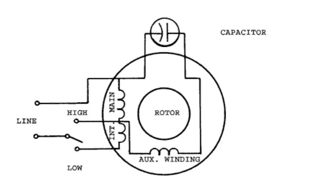
Here is the likely wiring diagram for your motor.
tmp9C23_thumb1_thumb.jpg

Notice that the difference between High and Low is just where in the winding the power is tapped in. In Low, you have more of the winding, higher impedance (ohms) so less current, less torque, slower speed. High speed is less of the winding, less impedance, more current, more torque, faster speed. If the breaker trips when you connect to Low, you likely have an shorted winding on that end. When you connect in High you are essentially bypassing that bad winding. Some energy may still be going to that short if it's a fault to ground, but because it's higher resistance than the High side of the winding, the motor still runs. If it is shorting to ground, it is dangerous.


" We are all here on earth to help others; what on earth the others are here for I don't know." -- W. H. Auden
 
As directed definitely hook a functional ground wire to the motor case!

Hooking the (H) to L gives 1140RPM and high the standard 1725RPM. You get one or the other.

Keith Cress
kcress -
 
Green goes to the frame for a safety ground, but check that the green wire is indeed a ground wire.
That is a two speed motor and if your green wire is not connected to ground then;
With White on Lo and black on Hi you would be trying to run the motor at two different speeds in two different directions.
Whith the Com-green wire properly grounded, the Lo speed winding will be shorted out and by transformer action the Hi winding will act as the primary with the lo winding shorted, and excess current will flow in the hi winding.
A 15 amp breaker will generally hold in long enough on the inverse time to start a 1/2 HP motor. The starting current is not generally enough to trip the breaker.
The green wire looks like it is grounded at the source. It will be at the same potential as the white wire so connecting the green to Lo effectively shorts out the Lo winding. Then transformer action gets you.

Bill
--------------------
"Why not the best?"
Jimmy Carter
 
Jeff Where did you get that diagram? It worries me a little.
660 RPM slip seems a little much for a 1/2 HP motor.
I suspect two separate windings, one four pole winding and one six pole winding.
That could give full HP at either speed and at the same FLC.

Bill
--------------------
"Why not the best?"
Jimmy Carter
 
Inrush currents for small motors are typically 6x the full load current. A 15A breaker may hold, but the traditional formula for a breaker is 2.5X the full load current. So, a 20A breaker seems reasonable in this case. Moreover, a GFCI protected circuit may trip on such a motor, so if you experience tripping events, you would want to eliminat ethe GFCI, if applicable.

 
BlackJackJacques -

In the IEC world our breaker ratings are available as a number of 'types': a Type B breaker has a instantaneous (magnetic) trip at 5x rating, Type C at 10x rating and Type D at 20x rating. For this application I'd pick a Type C. Are there similar MCB types in the ANSI/NEMA world?
 
Bill, it’s a 2 speed single phase diagram that fits what he said his terminals are. In the other type, the connection would be more complicated.


" We are all here on earth to help others; what on earth the others are here for I don't know." -- W. H. Auden
 
ScottyUK: We do have MCBs with adjustable instantaneous setings, but only in the commerical or industrial arenas. Residential CBs as may be the case for the OP with a small home lathe, do not offer such features. So in such cases, the solution is often upsizing the breaker. I wish we did, but the manufacturers seem to dominate code-making activites, and as such, drive what is available. Or as we say here in the states: Two things you don't want to see made: Sausages & Standards :)


Best

Jim
 
It’s not some conspiracy to influence code making. You can use a 3 phase motor protector unit and run the poles in series for single phase. Most smaller single phase motors have integral thermal protection, so the only place this is necessary is larger motors, which are more often industrial or commercial where the slight added cost of using a 3 phase protector is less relevant. So basically there is no real market for a purely single phase version.


" We are all here on earth to help others; what on earth the others are here for I don't know." -- W. H. Auden
 
That diagram looks like a diagram for a much smaller fan motor.
I don't think that either of us has ever seen a 1/2 HP motor using winding resistance to control the speed.
In much smaller motors the technique is used but the lower speed is dependent on the load. Mostly seen with fan motors sold as a motor fan unit. Such motors seldom list the lower speed on the nameplate.
If that technique were to be used for lathe control, the no-load speed on the LO connection would closely approach the speed on the HI connection.


Bill
--------------------
"Why not the best?"
Jimmy Carter
 
Status
Not open for further replies.

Part and Inventory Search

Sponsor