Continue to Site

Eng-Tips is the largest engineering community on the Internet

Intelligent Work Forums for Engineering Professionals

  • Congratulations Toost on being selected by the Eng-Tips community for having the most helpful posts in the forums last week. Way to Go!

Hertzian line contact in Solidworks FEA 1

Status
Not open for further replies.

RodRico

Automotive
Apr 25, 2016
508
I'm designing a cam driven engine. I do all the calculations in Excel then export the results as equations to Solidworks where I create 3D models and run analysis to confirm my Excel calculations. The Excel calculations related to the most heavily stressed cam (R1 = 0.290", R2 = 2.468", 2,768 lbf force) indicate peak contact pressure of 248 kpsi over a contact length of 0.993" and width (2b) of 0.014" yielding Von Mises stress of 231 kpsi. The material is Maraging 350 steel having 319 kpsi yield, 0.32 Poisson Ratio, and 29,733 kpsi modulus of elasticity. I have confirmed my 2D calculations with several on-line calculators, so I'm confident they are correct. The 231 kpsi Von Mises result is, however, uncomfortably near the 319 kpsi yield.
Capture_mtl0pa.jpg

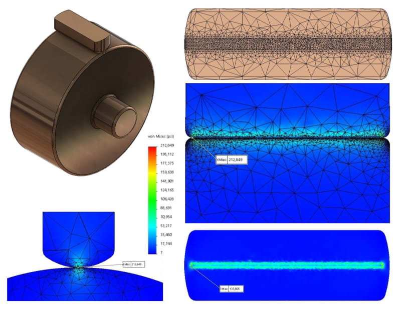
When I run the same conditions in Solidworks FEA, I get a peak Von Mises stress of 213 kpsi. At first glance, that seems to correlate well with my 2D Excel result of 231 kpsi. Unfortunately, the Solidworks result reflects a hot element, and the rest of the surface shows a much lower Von Mises stress, typically below 138 kpsi. I extracted the stress and contact force data from the contact patch and confirmed it is a 3D Mohrs Circle calculation.

My question is simply this: Should I trust the Solidworks 3D results or my own 2D calculations when evaluating the design for margin?
 
Replies continue below

Recommended for you

Try further increasing mesh density around the contact region and see how it influences results. You might also use adaptive mesh refinement. And see what happens when you use another type of contact (which one was used here ?).

If you have access to any other FEA software you can compare the results with those obtained in SolidWorks. Hertzian contact is a typical benchmark problem.
 
I was writing a lengthy post until I realized I didn't quite get what or where the problem was! So, what exactly is bothering you? Can you expand on that a little?

*********************************************************
Are you new to this forum? If so, please read these FAQs:

 
IceBreakerSours,

I do parameteric design based on Excel cals, and my cam parameters are evolved using Von Mises stress estimates developing using 2D equations. The result, however, is significantly lower in Solidwork's 3D FEA. If I accept the Solidworks result, I have significant safety factor. If I accept my 2D calcs I do not. I'm trying to decide which is more accurate so I have confidence in the operating life of the cam.
 
All,

Someone in the Solidworks forums pointed me to S-072286, "How do I simulate Hertz stress that results from contact pressure?" which states "Contact stress is a VERY LOCALIZED phenomenon. Capturing the phenomenon requires an EXTREMELY dense mesh in the contact area. It is difficult to capture with a 3D mesh. You should use the 2D Planar simplification when approaching this problem." It describes the classic formulas and solves a sample case which it then shows are nearly identical with the results from Solidworks 2D planar analysis. I don't really need visual verification of my 2D calculations; I've already checked them against multiple sources and on-line calculators. I'll just go forward with those results.

Thank you for your assistance!

Rico
 
To anyone having similar problems,

I found Solidworks 2D FEA yields results very similar to those from the free software from Vink System Design and Analysis. I use Excel to design my cams by generating splines which I export as XYZ points to a Solidworks curve, so I really need my Excel calculations of stress to be correct. I therefore examined every equation and found I had swapped X and Y in a few places. After correcting the errors, my Excel results are now the same as the free software from Vink. The corrected Excel calculations combined with a better estimate of Heat Release Rate (HRR) in HCCI combustion now result in 65% yield margin, so I'm a happy camper.

I have attached my corrected Excel calculations just in case anyone else finds them handy. The file contains summaries of the calculations as well as links to their sources.

Rico
 
 https://files.engineering.com/getfile.aspx?folder=1632cd26-93bf-4533-8847-72e5a31a5910&file=Hertzian_Line_Contact_Stress.xls
Status
Not open for further replies.

Part and Inventory Search

Sponsor