Eng-Tips is the largest engineering community on the Internet

Intelligent Work Forums for Engineering Professionals

Hi, I have to select a 12" ball ba 1

Status
Not open for further replies.

Ikramullah Shah

Mechanical
Jun 5, 2023
5
0
0
PK
Hi,
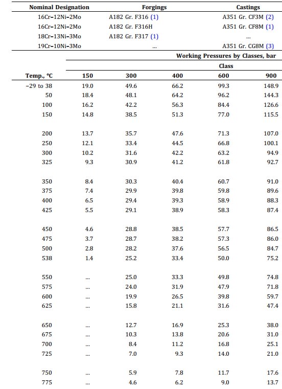
I have to select a 12" ball balve for DRI (Directly Reduced Iron) FEED legs, which supply DRI pellets (5 ~ 13 mm size) at 750 Deg. C. for further processing. These legs are connected on the bottom of reduction furnace where DRI is produced. Valve supplier proposes a material of A 351 CF8M for this high temperature. The proposed pressure class is 150 lbs. which has a maximum pressure of 2.8 barg. at this temperature. In our case, DRI is coming from shaft furnace via gravity. The quoted pressure is higher at valve inlet. This pressure is by virtue of static head of DRI column in shaft furnce.Therefore we asked the supllier to use a 300 lbs. valve. However, he is of the view that since this is not a gas or liquid flow, but a solid flow, the concept of leak tightness does not apply. The temperure is met, therefore we can use 150 class. I want to know, what will happen if a higher pressure is encounteded than the maximum rating of a valve flange. Apparaently, only the leak tightness of valve will be compromised,and hot air/vapor associated with hot DRI at 750 C will leak from flange. T Need expert avise on it from friends.
 
Replies continue below

Recommended for you

So you're trying to use a ball valve to deliver packets of solid material?

Can't quite see how that is going to work so fundamentally I think you have the wrong valve type, but at 750 C I'm not sure what you can use.

But anyway the question is about solid material force on the valve. Really not sure here whether the pressure from solid material applies in the same way on the flange surfaces, but I think at 750C you don't want to be taking high risks so I would stick with class 300

Remember - More details = better answers
Also: If you get a response it's polite to respond to it.
 
"I want to know, what will happen if a higher pressure is encounteded than the maximum rating of a valve flange. Apparaently, only the leak tightness of valve will be compromised,and hot air/vapor associated with hot DRI at 750 C will leak from flange"

This complex question, IMHO, pushes you into the realm of needing a structural analysis expert offering high-temperature FEA analysis.

"Need expert advise on it from friends"

I would not rely on the subjective opinion of any friend of mine, let alone the the bizzare opinions of faceless strangers...

You get the value of what you pay for ....

MJCronin
Sr. Process Engineer
 
I think what the supplier is suggesting is that 'some people are getting away with it'.
It doesn't sound like a good idea to me.

= = = = = = = = = = = = = = = = = = = =
P.E. Metallurgy, consulting work welcomed
 
@LittleInch

Thanks a lot for your reply.

The process designer Midrex USA uses ball valves for such applications. The supplier of the system proposes that a 150 lb. valve would be sufficient for this case, as here the leak tightening is not the concern with liquid or gas.

The valve metallurgy used, i.e. A 351 CF8M can withstand tempeatures in excess of 800 Deg. C. I just want to know, what may happen if the valve is operated at a pressure,a bit higher than max. allowable pressure the valve can sustain at this temperature. If pressure exceeds, the vapor associated with solid will leak to outside through flanges, and through its full despite closure of valve. As per my understanding slide gate type valve must be used, however, they do use ball valve, implying that mechanical forces of solids are not transmitted in the same way as with the case of liquid or gas. From the reduction furnace the flow converges into feed legs vis
a burdenfeeder located at the bottom of the furnace, hence its is not the case of a true hydrostati pressure.


@MJCronin, @EDStainless

Thanks for your responses.
I will further review this case and share results with you. The guidance provided by you people is valueable in further going intoit.
 
Ikramullah,

what table are you using?

Table 2-2.2 which is the only one with A351 Gr CF8M, has your 2.8 bar at 500C, not 750. The class 150 column stops at 538.

There is also a note saying CF*M needs to be carbon >0.04% above 538

So I don't understand how the vendor is claiming 2.8 bar at 750C??

I also don't understand why he's nickel and diming here for the cost difference between class 15 and class 300 valve...

Screenshot_2023-06-07_104842_b3ftmj.jpg


Remember - More details = better answers
Also: If you get a response it's polite to respond to it.
 
Then it's up to you.

Basically they are saying the valve itself is good for 1.4 bar at 750C, but the flanges aren't....

If there is a gate valve there what is the ball valve doing?

So you can accept it based on their letter ( essentially we've done this loads of times in the past and nothing has blown up yet) or reject it. Your call.

Still not sure why they don't just say Ok, but it will cost you $xxxx.

IMHO, they know they should be welding this valve in place or use a class 300 to make the issue go away, but can't be bothered. Do you need them more they need you?

Remember - More details = better answers
Also: If you get a response it's polite to respond to it.
 
Velan has been a reputable valve supplier, I would consider their service experience to have some worth, but I likely would ask questions about expected service life.

Reference the technical brochure If the MIDREX shaft furnace operates at a negative gas pressure or a very low pressure gas pressure will not be a significant driver of the the mechanical strength requirement of the valve. The OP does not state the operating pressure of the gas in the furnace.

Some guesses from looking at the letter, the valve drawing, and the little information on MIDREX's site.
[ul]
[li]The shaft furnace operates at a low gas pressure.[/li]
[li]The shaft furnace outlet consists of a slide gate and a ball valve that together act as an outlet lock (valve 1 opens, fills the space between the valves with pellets, valve 1 closes, then valve 2 opens, drains the pellets then valve 2 closes, process repeats).[/li]
[li]The valve diagram seems to have features intended just for this application.[/li]
[/ul]
These valves will eventually fail in service (even if the valves were fabricated from unobtainum), think about how operations or maintenance should handle the possible failure modes.

It helps greatly (shorter outage, less cost, safer workplace) when the staff knows how to handle expect-able failure modes, and has a plan and parts.
 
Status
Not open for further replies.
Back
Top