Continue to Site

Eng-Tips is the largest engineering community on the Internet

Intelligent Work Forums for Engineering Professionals

  • Congratulations KootK on being selected by the Eng-Tips community for having the most helpful posts in the forums last week. Way to Go!

High Impedance Earthing Transformers vs Neutral Earthing Resistors? 1

Status
Not open for further replies.

electrical429

Electrical
Nov 13, 2019
51
So in order to provide start point reference on a delta winding of a power transformer and limit earth fault current to a certain level you can either use High Impedance Earthing Zigzag Transformer or Earthing Zigzag Transformer + Neutral Earthing Resistor. Does it matter which option you choose? What are the benefits/drawbacks of using one or the other?

 
Replies continue below

Recommended for you

With a transformer, and secondary resistor, you can measure the voltage on the secondary to detect a ground fault on the system. Real important when the ground fault levels are below say 50 amps.
Sure beats using three PT's in a delta secondary.
 
Resistive earthing is a sub-set of impedance earthing. Some resistive earthing systems may be referred to as impedance earthing.
Once an earthing transformer system is selected, the choice is then what type of impedance to insert to limit the current to ground.

--------------------
Ohm's law
Not just a good idea;
It's the LAW!
 
Ok, but if you are limiting earth fault current to 1000A on a 33 kV side of 132/33 kV YNd11 transformer then I guess there is no difference between High Z ETx and Low Z ETx + NER.
 
The option you choose also depends on the magnitude of earth fault current that you want to limit to.
There is a design constraint in selecting a high value of zero sequence impedance for the zigzag transformer primary winding. So it may not be possible always to have only zigzag transformer without a neutral earthing resistor.
It is best to discuss with the transformer designer in order to find most optimum size for transformer and the NER, once you have decided on the maximum allowable earth fault current magnitude for the system.
 
One point to remember- when you add grounding transformer + resistor in series, only consider resistor value for the calculation of fault current. Z of the grounding unit will not contribute to limit the current.
 
prc,
I have seen zero sequence impedance of zigzag earthing transformer being factored in the earth fault current magnitude calculations. Do you think it is incorrect!
Could you please clarify, Sir!
 
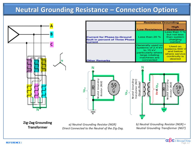
Electrically it is possible to connect to the artificial neutral of the zig-zag transformer either of the options (a) or (b). See the Illustration below.

No. It does not matter what option to use from the electrical point of view. However, economics and O&M issues should be further investigated.

1) The direct connection of the NGR to the neutral of the zig-zag transformer (Option a) is economical for low voltage applications such as high-resistance grounding where service continuity is desirable.

2) The connection of the NGR + NGT could be more economical for MV applications such as large rotating machines with low-resistance grounding. In this case, the resistor is rated for low voltage using an inexpensive single phase distribution transformer


.
Neutral_Grounding_Resistor_-_Connection_Options_eg3d4p.jpg
 
No Raghu, it is correct. Usually the fault current will be limited to low value(100-300 A ) when resistor is used. So resistor value will be quite high compared to reactance value of transformer. When they are added vectorially impact of transformer reactance will be almost nil. So text books simply put R= phase voltage / fault current.
 
You forgot to make mention of one other possibility, directly connecting a neutral inductor to the Wye point of the main power transformer winding. This is frequently done by utilities to reduce the single line to ground available fault current while still allowing the transformer to remain effectively grounded such that it can support single phase transformers connected between phase and ground/neutral. Typical sizes range from 1/4 ohm all the way up to 2 ohms for very large transformers such as 100MVA top rated.

A typical example is if you are trying to limit the fault current for fusible cutouts to around 12kA asymmetrical, in a substation with an 50.4/67.2/84 MVA 26.4kV transformer, say with 10.5% impedance and transmission about 25kA available at 138kV, you would have a 3-phase symmetrical fault current of around 10,000A and adding a 1/2 ohm neutral reactor that would get your single line to ground of about 7,500A symmetrical, 12,000A asymmetrical. In this way you could easily apply commonly rated 27kV 12kA rated cutouts to transformers and cable circuits knowing that the cutout will be able to interrupt a single 16,000A asymmetrical (10,000A sym) 3-phase fault with replacement of the fuse tube and link and will interrupt 3 times at 12kA replacing the link only. 3-phase faults are much more rare than single line to ground so this gives a good margin of protection without needing more expensive overcurrent devices.

You will also need to keep in mind how having a neutral reactor will change your earth fault currents if you are doing ground or neutral relaying.

As others have mentioned using resistors is much more common on low resistance grounded systems where you are trying to limit the single line to ground fault currents to very small values such as 400A. In this application, you cannot connect any loads between phase to ground as you are no longer effectively grounded. You will also need to make use of higher rated surge arrestors as your unfaulted phases will rise close to the phase to phase voltage on a single line to ground fault and you don't want faults to cause your arrestors to spark over.

Both inductors and resistors have duty ratings depending on how many faults they see. So they will become a maintenance item to keep an eye on and will need to replace after so many thru fault operations.
 
Status
Not open for further replies.

Part and Inventory Search

Sponsor