Eng-Tips is the largest engineering community on the Internet

Intelligent Work Forums for Engineering Professionals

High strain testing of contiguous steel piles? 2

Status
Not open for further replies.

LittleWheels

Structural
Nov 27, 2001
333
0
0
GB
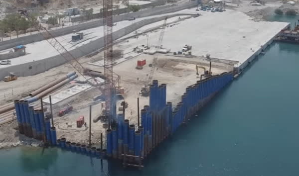
I have a pile wall composed of large diameter steel tubes linked by clutches and a very stiff capping beam.

I am concerned that clutch friction might increase the assessed capacity of a pile (tested individually) when in reality all piles in the locality would be loaded simultaneously and there would be no benefit from clutch friction. Probably clutch friction isn't a huge capacity contributor but somebody must already know the answer.

In addition, the soil between the CAPWAPed pile and the adjacent untested piles might be assessed as providing a greater resistance than would actually exist when the piles are simultaneously loaded.

Are there any papers examining the effects of the adjacent piles on the assessed capacity of a pile when it is high strain tested? I have not yet found such research.
 
Replies continue below

Recommended for you

LittleWheels - Interesting question. I'm not familiar with clutches, but they seem to be very stubby sheet piles with interlocks. Also, don't have pipe pile driving experience (as a former Bridge Contractor), but I do know about behavior of driven steel sheet pile interlocks... and I expect this would be similar.

There are studies about how driving is affected. Here is one: "Interlock Friction in a Steel Sheet Pile Wall: Laboratory Test". Soil type and soil saturation are the main factors for interlock friction during driving... but things change a day or so after driving is completed:

For various reasons, the interlocks really "seize up" and resist movement (either up or down). This is most apparent to a Contractor extracting cofferdam temporary steel sheeting. Often the sheet pile cannot be extracted without resorting to a trick... impact drive a sheet (or two) down a few inches to free the interlock and break soil friction on the pile. Then quickly (within a very few minutes) make the extraction... usually works well.

Not sure this addresses your questions, but IMHO, after all the piling are driven they are going to distribute and share load among the connected pile group (potentially compensating for any questionable individual pile), even without the stiff pile cap.

 
I think what you are describing is a combi wall, but can you upload a sketch of the configuration. How wide are your clutches? Are they just a single sheet pile between pipes?

Also, can you explain your testing/construction timeline. Were all pipes installed and then sheet piles driven between and welded above the mudline or where the pre welded and driven as one then adjacent welded.

Why would there be no benefit of the clutches when the piles are loaded simultaneously? Anything that is protruding into the ground is going to grab frictional resistance as it is pushed or pulled.
 
EC, not a combi-wall and there are no sheet piles involved at all.

The contractor is installing a long line of contiguous steel large-diameter tubular piles linked with clutches/ interlocks (terms used interchangeably in this part of the world) welded directly to the piles. The piles are driven into position. The pile diameter is virtually the pile C2C spacing.

High strain dynamic testing is being used to ensure that the driven pile's capacity is satisfactory under service loads. The testing is occurring to individual piles. The piles will be loaded as a group.

My concern is that the tested pile is possibly being supported during high strain testing by clutch friction to the adjacent piles and by the soil between the loaded pile and adjacent unloaded piles. In service, the piles will loaded simultaneously, so there won't be support provided by adjacent unloaded piles i.e. no clutch friction and the soil shear perimeter will basically be parallel to the pile wall = shorter. If so, the 'real' pile capacity in service may be lower than the capacity assessed during high strain testing.

Has anybody looked at the issue of individual loading vs. group loading in very closely-spaced piles during dynamic testing? If so, is this concern justified or has it been shown to be irrelevant?
 
A test pile was driven and tested. No problems with that.

The concern is with assessing the capacity of the installed piles which will have interactions with the adjacent piles when a pile is tested. When in service, adjacent piles will be loaded simultaneously, which is not how the piles are being tested. My concern is that the test pile (when within a line of piles) has 'an unconservative capacity assessment' because of the support of the adjacent unloaded piles.
 
Thanks for clarifying Little Wheels.

I was going to recommend the same thing a PEinc re testing a single pile.

I dont think dynamically testing a pile that is essentially connected to another pile is correct. There is potential for piles to interact given the clutch connection.

Also, side note, are they really contiguous if they are connect with the clutch..

 
I took 'contiguous' to mean 'next to' or 'touching'. That seemed a fair description for steel tubular piles installed clutch-to-clutch without intervening sheet piles (which would be a combi-wall).

The relationship between testing individual piles and testing piles within a group to find their resistance in service is what I am trying to understand.

It is not practical to carry out high strain testing of multiple adjacent large piles (approx. 1500mm dia.) simultaneously.

We have high strain tested an individual pile without any nearby piles and it achieved the minimum resistance for the design. We are high strain testing a percentage of piles within the pile wall and these results are achieving the minimum resistance for the design but not by a very large margin. At first glance, the results tick the box and the pile capacities seem satisfactory but there is a concern that the tested pile wall piles have 'artificially-high assessed capacities'.

The piles are driven one-at-a-time and tested one-at-a-time but the pile performance is probably influenced by the adjacent piles. It seems possible that the assessed capacity of the installed piles (tested one-at-a-time) is higher than the actual pile capacity when they are simultaneously loaded. Simultaneous loading is how the piles will be loaded and is the critical capacity.

The only information I have found for larger tubular pile groups have spacings in the range 2-5 pile diameters. We effectively have a spacing of 1.
 
to be honest i dont have much more to add other than that I think testing piles that are connected to another is a flawed approach. testing a percentage of piles with dynamic testing is common practice but i dont think its very common to test piles like you are on your project.

What is the project, what is being built on top of the wall? is this a retaining wall that is also carrying axial load?
 
Yesterday, I received a foundation design report for a highway bridge project where the DOT's engineer ran a WEAP analysis for sheet piling expected to be driven with a vibratory hammer. I am sure their analysis is flawed for at least two reasons: 1) the analysis ignores and cannot address the effect of the sheet piles being interlocked when they will be driven and 2) the WEAP analysis considered driving single Z-sheets when, most often, contractors drive sheets in pairs (doubles). So, it seems that at least one engineer and the DOT have totally ignored any effect from the sheet piling being interlocked. This may be wrong but I don't see another way of testing a sheet pile unless a single or double sheet is driven without connection to previously driven sheets.

 
PEinc - Everything you have stated is absolutely correct.

Pile spacing of 2-5 diameters, which the OP referenced, is to minimize pile interaction (through soil). The most common example of pile interaction through soil is how a displacement pile being driven can cause "heave" of nearby, previously driven piling. As I said in my first (apparently invisible) post, a connected pile wall (sheet pile or pipe) works under load as a single unit and performance exceeds the sum of the individual piles.

To revisit interlock resistance, it is also "real" during driving. In fact, which way the interlock is oriented can make a significant difference. "Male" interlock should be the leading edge (i.e. not engaged with another sheet during driving). If "female" interlock is leading, soil will "clog" the interlock, increasing resistance when the next sheet is driven.

It's stated that the Contractor is driving one pile-at-a-time. This is called "Pitch & Drive" and is the fastest, cheapest way (for the Contractor) to drive sheet piling. Pitch & Drive often results in pile walls that are marginally in dimensional tolerance (or worst).

The best ways to drive a wall (or cofferdam) are "Panel Driving" or its variation "Panel/Staggered" driving. In both case, all piles are set and the entire wall is driven in segments like the screen shot and short video shown below:

Pipe_pile_wall-600_gjasba.jpg


Panel/Staggered Driven Connected Pipe Piles Video
 
SRE, the pipe piles are driven in panels. You are correct about male before female in driving reducing soil packing. You are correct that closely-spaced piles works under load as a single unit. I have not yet found evidence for the wall exceeding the individual pile capacity summation.

Comparing sheet piles and 1500mm dia. piles suggested to me that interlock friction would be a smaller percentage of driving resistance for large pipes than for sheet piles.

Interlock friction will increase the assessed capacity of a single pile within the pile wall (as is being tested on site). Simultaneous pile loading does not provide the benefit of interlock friction. Doesn’t that situation mean that the assessed capacity is lower than ‘reality’?
 
LW - I agree that interlock friction is less of a factor on 1500mm diameter pipe piles than steel sheet piling. But there is more to it than friction. I know there are no accurate answers:

1) How "straight" are the interlocks fabricated (welded) to the pipes. There will be a certain amount of "binding" because of trivial deviations over the length of connected interlocks.

2) Because of small movement below grade after driving, any given piling is "wedged" between two adjacent piling making any movement difficult.

3) A certain amount of soil will work its way into the underground interlock... not much, but enough to really freeze the interlock.

Then there is the stiff pile cap. Even a point load will be distributed over more than one pipe pile.

The real "wild cards"... are these point bearing or friction piling and what is the embedded length of the piles in soil?

If point bearing, to what degree... driven to absolute refusal (competent rock) or just driven to practical refusal (high blow count). The next question would be are the pipe piles filled with concrete, increasing pipe pile bearing area.

If there is some tendency to settle (practical refusal), there will likely be soil's skin friction on the pipe wall (even though it was ignored for design of point bearing piles).

If friction piling, deflection under loading will pick up not only whatever interlock resistance is available, but also soil's skin friction on the pipe wall (that increased after driving ended). And of course, an "small" deflection of an individual pile will force the stiff pile cap to distribute some of the load to adjacent piling.

IMHO, a well designed pile wall has many unintended (but beneficial) interactions going to increase load carrying ability beyond calculated value.

The test pile (per PEinc) will be a better guide to what to expect than high strain testing. I would look as much or more at the driving record for this pile than results of the load test. Same as the subtle information that an index pile provides about driving conditions, even though there is no formal load test.


The contiguous tubular piles form a quay wall around 400m long and support large rail-mounted quay cranes.

The interlocks/ clutches are accurately welded straight and parallel to the pile centreline. I agree that interlock friction is transferring applied loads to adjacent piles when an individual pile is tested and that any misalignment of piles (impossible to completely avoid during driving) increases interlock friction.

The pile design is a combination of end-bearing and friction, driven to a specified resistance (not practical refusal). High strain testing is several days after driving to allow set up to occur.

The piles are sand-filled at low levels and concrete-filled from below tie rod level to increase end bearing resistance.

The wall design already allows for the benefit of the stiff capping beam spreading concentrated loads across several piles in determining the minimum required pile capacity.

The risk is that the high strain testing on individual piles is identifying an artificially high pile capacity as, once the capping beam is in place, there is no beneficial interlock friction (or potentially enhanced soil resistance between loaded and unloaded piles) when in service loads are applied.
 
Seems you are doing everything right, and the piles should be near steady-state when high-strain testing is performed. Look for patterns in test data. If there is a questionable pile, test results for that pile will be different from "typical" piles. I can't say what "different" means, but should be obvious, if you look for variations. A good time to use "fuzzy logic".

Other than that, make sure the hammer is sized (energy) right and is operating properly. I learned both from my father and first-hand that a hammer can appear to be working correctly, but not delivering expected energy.

I really think problems will be few and you will be able to detect / address them in a timely manner.

 
I believe that the high strain tests may be fairly consistent (and the few high strain tests done so far are) but also that the results may consistently be artificially high, because of interlock friction and potential soil interactions with adjacent piles that are not able to be simultaneously loaded during high strain testing. If this supposition is correct, the pile wall may have less load capacity than the design requires.

I guess information on sheet pile interlock friction after set up can indicate one component of the pile interactions that may unrealistically boost a high strain tested pile's assessed capacity.

I am still trying to find applicable information regarding pile interactions where the pile-to-pile spacing approximates the pile diameter. Does a very closely-spaced pile group reduce or increase a single pile's high strain tested capacity? If it reduces the tested pile's capacity, the test result is conservative and my concerns go away. If it increases the tested pile's capacity, the designer may need additional skull-sweat.
 
LittleWheels said:
If this supposition is correct, the pile wall may have less load capacity than the design requires.
You are correct but considering that driven pile safety factors for ASD are usually pretty high or resistance factors for LRFD are usually pretty low, capacity problems should not be expected if the piles are driven as required.
SlideRuleEra has given you some very good and practical comments.

 
No arguments about that PE but a general 'FoS means everything will be fine anyway' is quite difficult contractually.

It is surprising to me that nobody seems to have published about or even actually examined whether high strain testing is meaningful for close-spaced tubular piles. This can't be the first time this question has come up.
 
LittleWheels, I would be greatly surprised if there is anything written in a book or paper about testing interlocked piles. If you are required to test a single pile within a row of installed, interlocked piles; go ahead and test it however required. Just remember that the "capacity" results are probably meaningless unless used just for comparison with other tested, interlocked piles in the same wall. The testing could indicate potential pile problem areas but not real, individual pile capacity. In my opinion, the only reasonable test is for a single, not interlocked pile that has been driven and tested as closely as possible to the proposed wall but either in front of or behind the wall, not in the line of the wall. And, be ready to explain to the powers-that-be the problems of testing an interlocked pile. Load transfer through an interlock can be great due to friction in a tight interlock, from soil jammed into the interlock during driving, from a poorly manufactured or misaligned interlock, from a pile that has s bend or a sweep when driven, and from very hard driving that can easily weld the interlock.

 
The problem is that the high strain test results for interlocked piles may have different meanings.

What do you think of the following thought experiment?

A percentage of the piles are high strain tested and every tested pile indicates that it has the minimum required resistance only. Interlock friction may vary from zero to completely locked under the test load.

If the interlocks are frictionless (unlikely) and there is no soil enhancement interaction with adjacent piles (doubtful), then the high strain pile result reflects the capacity of only the pile tested and that provides useful information. Probably the pile wall has sufficient load capacity, assuming that the untested piles have capacities similar to the tested pile.

If the tested pile has zero capacity and the interlocks are fully locked by friction such that any applied load is completely transferred to the adjacent piles (together providing at least the required resistance for a single pile), then the high strain test result has reported that the pile has satisfactory resistance when in reality that particular pile has no resistance. Driving records would identify significant differences in pile resistance during driving.

If the tested pile actually has 1/3 the resistance required, as do the adjacent piles, excessive interlock friction may incorrectly indicate that the tested pile has sufficient capacity alone. Because of similar driving results, it may appear that all three piles have the required minimum capacity to meet the wall design's requirements when in reality, none of them do.

Driving records would need to be interpreted to infer the actual pile capacities, without the benefit of set-up. The high strain test results of the original isolated test pile (away from the wall) would have to be used to estimate set up, as is normal practice.

If interlock friction increases as pile driving progresses, then the effects of interlock friction (transferring the driving forces to the adjacent piles) alone could mimic the pile achieving the expected resistance during driving, despite the driven pile itself having zero capacity and the two adjacent piles each having only half the required minimum capacity.
 
Status
Not open for further replies.
Back
Top