Eng-Tips is the largest engineering community on the Internet

Intelligent Work Forums for Engineering Professionals

  • Congratulations waross on being selected by the Tek-Tips community for having the most helpful posts in the forums last week. Way to Go!

High vertical vibration amplitude

Status
Not open for further replies.

indoldrums

Mechanical
Aug 15, 2014
11
0
0
US
Hello all,

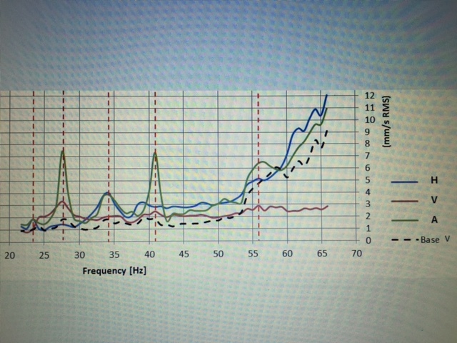
We are trying to troubleshoot a vibration issue with our motor-compressor drivetrain. The issue is that when we run a coast-down from 3600rpm down to the min speed, we get high amplitdue vertical vibrations (7mm/s RMS) at about 1500rpm and 2400rpm. Horizontal and axial vibration levels at these modes are low, less than 4mm/s RMS.

Does anyone have any ides why we may be seeing high amplitudes in one direction only, and what could we do to lower the vertical amplitude down? Thank you!
 
Replies continue below

Recommended for you

Is this equipment on vibration isolators?

TTFN
faq731-376
7ofakss

Need help writing a question or understanding a reply? forum1529


Of course I can. I can do anything. I can do absolutely anything. I'm an expert!
There is a homework forum hosted by engineering.com:
 
You have not given much information for us to assist you! The vibration natural frequency/mode can be from deflection of the motor/compressor on the base frame/skid, but perhaps more likely from compressor suction or discharge piping (including valves and pulsation dampers). If you can run machine steady at each speed, then an operating deflection shape test could be conducted. If the machine can be shut down, then you can conduct an impact test (impulse-response method). There are other tests and measurements that could be conducted with machine running at normal speed as well.

Walter Strong
 
Let me try to elaborate more.
We are measuring the vibration on the NDE motor foot. We are also measuring the base skid that the drivetrain is attached to, near the NDE. Base skid vibrations are not nearly as high as the motor foot vibrations. This makes me think that isopads are doing their job.

Based on the bump test and modal fea analysis, we can see there are modes aligning with the 1500rpm(25Hz) and 2400rpm(40Hz) and some others but I am mostly interested in these two modes as they exhibit high, vertical only vibrations. Operating range of the motor is 1200rpm (20Hz) to 3600rpm(60Hz).

I don't know if it is even feasible to move these two modes out of the operating range, or if there is anything that can be done to lower the levels.
 
You appear to have some data and an son idea as to what the problem is, but you don't know how to solve it. Are the isolation pads directly under the motor feet? If so, this would be unusual. Typically the motor and compressor would be mounted/bolted directly to a steel frame, possibly filled with concrete to increase seismic mass, and then the frame is supported on isolation pads or spring mounts onto the primary foundation. The three basic choices for detuning a structure are mass, stiffness, and damping changes. There is no way of knowing what would be appropriate for your structure without knowing a lot more about it. Part of the challenge of modifying the structure is to avoid creating a new problem while solving the current one!

Walter Strong
 
Walter,

You are correct. I have some data, and an idea of what the problem is but I think I need to investigate more in order to come up with the right corrective action.

In this case, the motor is tied to the isolation pads and the isolation pads are tied to the steel frame which sits on the floor. Unfortunately, I don't have any flexibility to change that structure.

Thanks for your help!
 
Hi Greg,

Thanks for your feedback. I would like to invest some time into this problem and do it right and learn something in the process.
I am attaching the plot we took at the NDE motor foot. We have a pretty good match with the bump test results and this coast-down plot. This tells me that my issue is likely to be a structural one. As Walter mentioned it above, I have mass, stiffness and damping to play with but I am not sure what's my next most logical step should be in addressing this. You guys can tell I don't have much experience in applied vibration but I do enjoy problem solving.

IMG_2635_kxo4p6.jpg
 
I assume the motor is coupled to the compressor.
What make and model of coupling?
What type of compressor?

How much do the isolators deflect when the motor is placed on them?

Was the motor originally bolted hard to the steel frame?
Is the compressor bolted to the steel frame?
How is the steel frame attached to the floor?

Pictures are always nice.
 
Hi Tmoose,

I don't have access to the machine right this moment for pictures but I can briefly explain the setup:
The motor is bolted to the rotary compressor with a steel adapter piece. There are four isolation pads, two on the compressor and two on the motor side. This entire assembly is then bolted to the steel base frame. Base frame, however, is not bolted to the floor. I will have to check to see the make and model of the coupling.

Isolators deflect about 0.003-0.005in. Overall height of the isolator is about 2in. I need to check the transmissibility ratio again.

Thanks for your help!
 
Unless I am getting color blind in my old age, it looks like the green trace has two peaks at 7 mm/sec, and that trace is marked Axial! You also stated that machine speed is 3600 rpm (60-Hz), but the data plot extends above 65-Hz! I would like to see pictures and machine component nameplates. What instrument puts the vertical axis label on the right; perhaps plotted with Excel?

Walt
 
I'd start by doing a modal analysis, if you have a force hammer, or else plot operating deflection shapes, using a tacho pulse s a phase reference- actually this is likely to be more informative.

This will give you an idea of the x y z deflections along the major axis of the machine, and confirm what we all suspect, that it is just rigid body motion of the two major components, moving as one.

It is probably worth measuring the frame side vibration at the isolators as well, just to make sure you have a rigid foundation, this may be your 'Base V' plot. I agree with Walt, is A axial? If so and that is what you want to cure then it is more complex - 42 Hz looks to be purely axial.


Cheers

Greg Locock


New here? Try reading these, they might help FAQ731-376
 
Well, this is embarrassing because I mislabeled the axial and vertical plots. The green curve is the vertical (incorrectly labeled as axial on this chart) and the red curve is axial (incorrectly labeled as vertical). Sorry for the confusion.
Also, the Base V plot is the vibration on the base frame, in the vertical direction, near the isolation pads.

We ran the machine up to 4000rpm with a VFD. I believe the idea was to see vibrations 10% beyond the normal operating range.

I will take a closer look at the force-hammer tests we ran on all three axes and report back.

Thanks for all the help!
 
"Isolators deflect about 0.003-0.005in."

For a simple system That would be too stiff (too little deflection) to function as an isolator ( reducing transmitted vibration, at the expense of somewhat higher equipment vibration ).
Table 1, page 5 here -
file:///C:/Users/Robyn%20Timberlake/Downloads/20070727_simmons.pdf

0.003" static deflection translates to about 3400 cpm / 57 Hz resonant frequency.

With the mounts directly under the equipment feet the "foot print" is kind of narrow, inviting other degrees of freedom like horizontal rocking to join the party.

Vertical and horizontal Amplitude and phase info from all over the machine, steel frame, and floor at the various test speeds would be what I'd do next.

“Data!data!data!" he cried impatiently. "I can't make bricks without clay.”
Sherlock Holmes in, The Adventure of the Copper Beeches
 
I double checked the isolation pad deflections for the test setup that produced the vibration plot above, and found out that the average deflection for all four pads was 0.065in. IRstuff, when we tested the system with the stiffer isolation pads, which have the lower deflection I was thinking of earlier, the peaks and frequencies were little changed.

Tmoose, you are correct that the isolation pads are too stiff; I think that is the case even with the ones that have 0.065in deflection. The article you attached suggests fd/fn to be a minimum of 3.5 at the lowest fd. In this case, we are at fd=20Hz (minimum driving frequency)and fn=12.5Hz (isolation pad frequency), which is 1.6. Basically, we are hardly transmitting anything to the base until we reach a driving frequency of 45Hz, probably.

I think the reason the isolation pads are the way they are is because there was some effort to reduce the noise being transmitted to the base frame, to lower the overall noise level of the machine. Not sure if that was the right approach but I think it's wort re-testing with softer isolation pads.

Thanks for everyone's ideas and suggestions. I will be collecting more data next week.
 
The chances are high that plot, got from force-hammer test, will show different values for the peak frequencies...
Does anyone want to bet 10$ on the contrary (that frequencies will remain the same) ?
 
amanuensis, what are your thoughts? I would like to hear your take on this.

Also, just a general question; when I look at a velocity vs. frequency plot along with the bode plot from a hammer test, is it fair to say that for a frequency to be a resonant one, there must be a 180deg phase change?
 
Status
Not open for further replies.
Back
Top