Eng-Tips is the largest engineering community on the Internet

Intelligent Work Forums for Engineering Professionals

  • Congratulations waross on being selected by the Tek-Tips community for having the most helpful posts in the forums last week. Way to Go!

Hinge Joint FEM

Status
Not open for further replies.

Lee.Conti

Automotive
Nov 8, 2019
87
0
0
SG
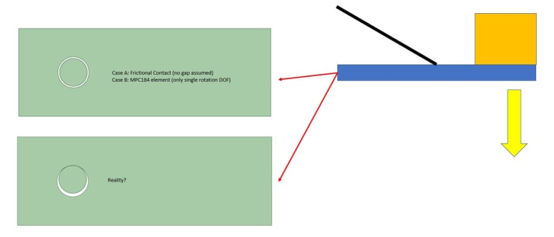
I am modeling a cantilever beam to carry a weight with a support (black line).

I want to check the impact of modeling the hinge at the end... if I use MPC element to allow rotation, I can almost two times deflection downwards from frictional contact at the hinge.

I understand in reality, there is a tight gap between the pin and hole... and the touching area should be at the top... which approach is more reality? Thank you!

Joint_p53abl.jpg
 
Replies continue below

Recommended for you

If the absence of the effect of the pin gap is leading to issues in your results, you could try adding a CBUSH at the end of your beam, calculate the spring rate by assuming the deflection is sufficient to close the gap under the applied load.
It's not the perfect solution but it should get you reasonably close.
 
A propped cantilever is s simple problem to solve, a propped pinned beam is even simpler (being statically determinate). Those are the two bounds of your problem, choose partially fixed if you want to.

How to FEA this (simple problem) ? ...

1) fix the end (all 6 dof),
2) pin the end (3 dof),
3) rather than a "sticky" CBUSH, I'd combine portions of these two cases to make a partially fixed support.

another day in paradise, or is paradise one day closer ?
 
Status
Not open for further replies.
Back
Top