Continue to Site

Eng-Tips is the largest engineering community on the Internet

Intelligent Work Forums for Engineering Professionals

  • Congratulations KootK on being selected by the Eng-Tips community for having the most helpful posts in the forums last week. Way to Go!

[Historic] Convert 25 Hz end of Frequency Changer to 60 Hz Synchronous Condenser 4

crshears

Electrical
Mar 23, 2013
1,786
Hey all,

I only recently learned that the synchronous condensers I operated at one site some 40-ish years ago were previously 25 Hz/60 Hz frequency changers, and that when Ontario's frequency conversion program to 60 Hz was completed, the 25 Hz end machines were rebuilt to 60 Hz synchronous condensers.

I cannot find any records of how this would have been done, and it never occurred to me to look it up at the time, mostly because I just accepted their presence at face value and never inquired at the time as to why they were there . . . and it now surprises me that nobody said anything about this to this lowly trainee at the time.

My speculative WAG is that the rotor could have been either replaced or the extant one rebuilt to operate satisfactorily at 720 rpm instead of 300 rpm, and that the windings would probably have been reconfigured form series to parallel operation in some fashion so as to address the cumulative voltage rise issue.

What I'm wondering about, though, is whether the stator lamination thicknesses would have worked in this new configuration, if there would have been eddy current and other loss issues that this would have caused, etc., etc.

Thoughts?
 
Replies continue below

Recommended for you

There are some incremental gains to be made by messing with lamination thickness (and silicon content) for various rotating machine designs. For the most part, it becomes cost-prohibitive to use the really thin (< 0.355 mm) material due to the increase in labor cost and the additional "care" in handling the thinner material to prevent warpage. That being said, pretty much everything below about 100 Hz uses one of two sizes: 0.635 mm or 0.470 mm. The pole steel laminations for the synchronous rotor would - most likely - have been up around 1.8 mm thickness.

To rebuild for 60 Hz would require a change in the rotor pole count - which may or may not have meant a complete new rotor from the shaft out. To rebuild for a condenser application would have meant increasing the thermal capability of the rotor winding considerably - or just reducing the overall output rating. The stator core may or may not have required new geometry - depends on what the slot count was.
 
Was the 25 Hz end disconnected? If it was stand alone, just feed it 60 Hz and it will turn faster.
Check my math, but I see 300 RPM as the highest synchronous speed that is common to 25 Hz and 60 Hz.
Two solutions:
1. Disconnected, run it up to 720 RPM.
2. Still coupled up to a 60 Hz machine, rewind or reconnect for 24 poles.
This leads to three possible issues.
a) Most serious, both the rotor and the stator must be suitable for changing the pole count.
This may be insurmountable without replacing the rotor.
b) The slots must line up in such a way that the outputs of both the 25 Hz end and the 60 Hz end must be exactly in phase. Any phase difference will lead to one machine motoring and the other generating.
c) Wave form.
Not that important,
BUT
It is not uncommon for a generator output to not be a perfect sine wave. The waveform is composed of contributions from individual coils that reach their peak voltages at slightly different times, If the two ends. 25 Hz and 60 Hz use identical cores then there will be no problem.
How serious is paralleling non matching wave forms? Not very. It is a common occurrence. It leads to a slight increase in losses at no load. This transitions to a slight inter-cyclic ripple in load sharing once the load exceeds the no-load circulating current.
This is something to know and then forget, but if a problem leads to trouble shooting by scoping waveforms, it is well to be aware of the possible issue.

What I'm wondering about, though, is whether the stator lamination thicknesses would have worked in this new configuration, if there would have been eddy current and other loss issues that this would have caused, etc., etc.
Chances are that the same laminations and conductors were used for both ends.
But if the laminations and conductors are not the same, there may be increased losses which may be addressed by
de-rating slightly.
 
Last edited:
Here is an interesting post, concerning 25hz/60 Hz synchronization.
The entire thread may be good background information.
Years ago I read an article in an engineering magazine about a 60 Hz to 25 Hz conversion.
A plant had a large 25 Hz induction furnace.
The utility was phasing out 25 Hz service.
Management looked at the cost of converting the furnace to 60 Hz and looked at the cost of a new 60 Hz furnace.
Then they asked the engineers if there was any way that they could devise to keep the furnace in service at minimal cosy.
They had a large inventory of spare motors, 25 Hz and 60 Hz.
Many of the motors were synchronous motors.
The solution; A 60 Hz to 25 Hz MG set built with on hand, spare motors.
The second challenge was capacity; They did not have any individual generators of sufficient capacity to run the furnace.
The solution was to run MG sets in Parallel.
The third challenge; Synchronization.
With synchronous machines, the phase angles were locked no matter what the relationship.
The solution; They fabricated a coupling with an adjustable angle.
The sets would be run and the phase relationship observed on a scope.
The sets would then be stopped and an adjustment made on the coupling until the phase angles coincided.
The fourth challenge; Again a synchronizing issue.
if the 60 Hz motor synchronized or locked on the wrong pole set, the 25 Hz side would be out of sync.
The solution;
Both sets would be started and the 25 Hz scope observed. If the scope indicated out of sync, the starter or the field on the 60 Hz motor would be opened until the scope indicated that the 25 Hz side was in sync.
The induction furnace continued in service.

Heritage: Early 20th century power generation​

https://www.eng-tips.com/threads/heritage-early-20th-century-power-generation.479341/
 
Decoupled; end rating was four separate synchronous condensers rated @ 30 MVA each.

waross wrote: Disconnected, run it up to 720 RPM.

240% increase in rotational speed would generate cubed magnitude centrifugal forces, no? Machines were air cooled, and unfortunately I cannot say for sure if the rotors were smooth or salient pole, although I have a vague recollection they were smooth.

Search on https://www.lifebynumbers.ca/history/the-rise-and-fall-of-25-cycle-hz-electricity-in-ontario/ for Scarborough Transformer Station. Interestingly, these pages say there were actually three frequency changers there at one point, meaning there would have been six machines in there . . . which explains why there was all that room at one end of the building, seeing as how by the time I got there only four machines remained. In the article, on the right hand side of the picture of the condenser building [ now demolished ] at Scarborough TS you can see a big black door in the wall; there was a rail siding that led right inside the building to facilitate component transport by Schnabel car. There was a heavy duty overhead crane in the building for maintenance and installation / removal purposes.

All the machines had ring oiled bearings, and seemed to turn near the same speed.

Building temperature was controlled by manually opening and or closing air inlets at ground level that were ducted to the machine cooling air intakes; these were fitted with proportioning dampers, hinged at the top, that could be set up to draw in only outdoor air, all recirculated air from within the building, or any desired proportion in between; and exhaust dampers in the windows higher up. One could never cool the building below ambient, of course, but in the winter if the building was kept boxed up only one machine was needed to keep it comfortable inside - - provided it was not run at zero MX for an extended period of time.
 
Stator core of that era will be hot rolled silicon steel with higher loss than the later day low loss cold rolled steel. So, core was most likely changed.

I doubt the 300 RPM rotor can withstand centrifugal forces at 720 RPM, so possible new rotor, bearings and bearing supports.

Stator winding should have been reconnected for 720 RPM for the original 300 RPM voltage or possibly rewound for any desired voltage.
 
My take would be that someone is likely confused on what happened 75 years ago.

It's likely that the 60Hz synchronous motors were just decoupled from the 25Hz generators and then used as the synchronous condensers while the 25Hz generators were scrapped or elsewise disposed of. They probably had a spare 60Hz motor that they installed as the 4th unit.
 
Certainly could be, Lionel, although the creator of the post credits someone from the former Ontario Hydro who may have had access to the documentation, either way it's tough to confirm.

The article mentions a vertical shaft frequency changer being removed at Chats Falls and being installed Sir Adam Beck 1, that is almost certainly the one I heard of and posted about in that Electrical Protection of Synchronous Condensers thread. The reports don't of course match precisely but the truth is likely in there somewhere.
 
Almost universally yes, common multiple of 2.4, with "pole slipping" / field polarity reversal used prior to parallelling to get multiple parallelled machines to a point where they would share load quite proportionately, if not always perfectly.

As to the not quite universally, there were isolated "bastard 25" machines supplying some loads out there with a seven pole set motor on the 60 Hz side and a three pole set generator on the other side, if you care to you can do the arithmetic for yourself. Yes, the supplied machinery ran a little faster than on actual 25 Hz power, but not unacceptably so.

Some locations had one or two FCs equipped with hydraulically actuated stator shifting which, when used in combination with pole slipping, permitted slow but infinitely variable loading adjustments for that machine; I'm pretty sure I have copies of the operator training manuals for those; the one I have to hand at the moment has a chapter on rotating machines that mentions them but doesn't get into the nitty-gritty.
 
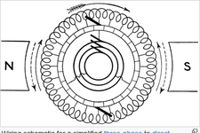
From Bacon4life's post. Small derivations of that are still in use.

oScreenshot 2024-12-16 at 07-50-18 Rotary converter - Wikipedia.png

Older diesel generators used a shaft mounted DC exciter.
The DC from the brushes was fed back into the main field with slip rings.
Many of the older machines were converted into brushless exciters by tapping the armature winding in three places and removing the commutator and brushes.
The three phase output was fed directly to the rotating diode plate and from there to the main rotating field.
While the original exciter could be used as is, the commutator would be removed.
Rather than insulate and restrain from mechanical force the connection to each commutator bar, it was cheaper and quicker to strip the existing winding and rewind the armature with a similar winding.
New winding notwithstanding, electrically the exciter would work with the original winding and commutator still in place.

These machines were originally Telco take-outs that were refurbished and converted and found new homes as standby generators.
They were typically resold to private business and residences for standby use.
Most of them are probably still in service despite their age.
The drawing shows that a DC armature may be tapped in three places to extract three phase AC.
In the conversions, the slip rings were not needed as the load, that is, the diode plate and the main field rotated with the armature.
 
Yup, found the 1965 Operator Qualification and Development document; pole slipping on driving machine and field polarity reversal on driven machine were performed, in combination with stator shift on one machine of each pair, to obtain synchronization before loading. At most sites, all but one FC would be equipped with stator shift.
 
I once encountered a very old gen-set with a mechanical AVR. It looked like military, possibly WW2 or earlier.
 

Part and Inventory Search

Sponsor