Eng-Tips is the largest engineering community on the Internet

Intelligent Work Forums for Engineering Professionals

  • Congratulations waross on being selected by the Tek-Tips community for having the most helpful posts in the forums last week. Way to Go!

Hmm Two Phase into Three Phase 1

Status
Not open for further replies.

7carisfast

Electrical
Jun 15, 2004
48
0
0
US
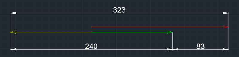
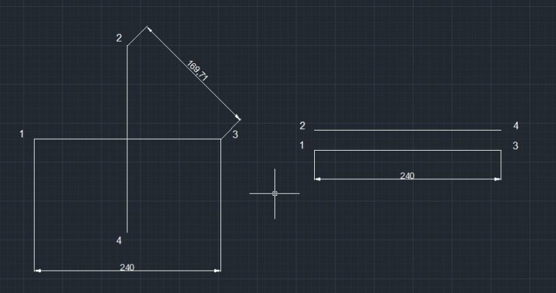
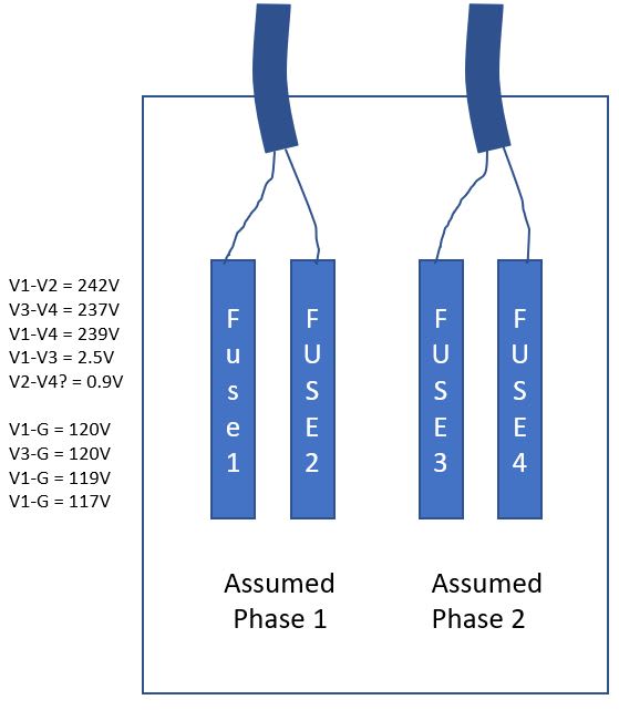
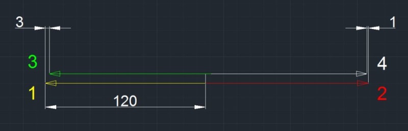
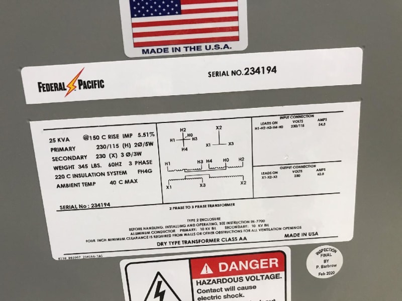
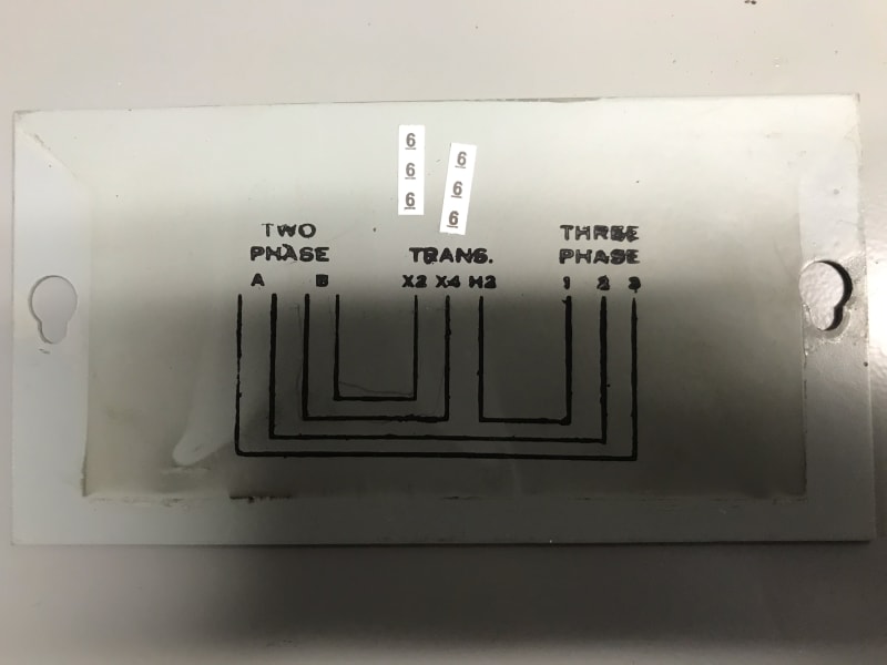
We have a customer in Philly who currently has an old 2 Phase system (which history tells me has a phase shift of 90 Deg). These systems used to be popular in Philly and still existing in some areas. For years, the customer had what appears to be a single phase buck-boost transformer to turn their two phase system into a three phase system (solely for the purpose of a 3 phase HVAC on roof). The buck Boost phase is what they used to call a teaser leg to my knowledge and is commonly referred to as the Scott configuration. PECO did some line work and within 1 or 2 weeks, this single phase transformer blew. They purchased a 2 Phase to 3 Phase transformer from Federal Pacific, but upon checking the secondary, they measured 240,323 and 83V. Federal Pacific suggested replacing the new transformer with another new unit, but the results were the same. They were on the phone for literally for 3 hours providing onsite values.

It's of my opinion that PECO upgraded the system to a modern day system with a 120 Deg phase shift. No one in the area/block has issues as it's residential and they only have single phase services. Could this be the cause of the failed unit (besides age) and the bad readings from the new transformer(s)?

c005cd4a-c782-4d60-8ea5-2e95a5bccae6_anzuxl.jpg
33440c7a-5b58-446c-8e46-c9fc0030577f_urqvbo.jpg
 
Replies continue below

Recommended for you

Phone PECO and ask them.
More guesses won't help.
As well as upgrading to three phase, they may have changed the configuration of the two phase system.

[link ]Bill[/url]
--------------------
"Why not the best?"
Jimmy Carter
 
The 2 ph system is 5 wire as the trx implies?

First picture is clear, but what it that diagram on the plate of the second picture?

It doesn't correspond to the transformer connections on the first picture. I can't make sense of it.
 
The second picture is the wiring diagram that was on the failed unit (original) that worked for years. And yes, it is a 5 wire system. Thank you guys.

EDIT: I assumed it was a 5-wire system, but now that I think about it, I only saw 4 wires in the fuse box, I would have to imagine there is a ground.
 
For the voltages measured in the secondary, it looks like the voltages are in phase (or opposite phase), like this:

Scott-sec-voltages_eyx76l.png


If secondary voltages are in phase, primary voltages must be also, so chances are that the transformer is fed with a duplicated single phase instead of a proper 2-phase, 90º degrees apart.

2-ph_voltages_nepfu8.jpg


Check the primary voltages, between the two phases the voltage should be √2 x 120 V = 169.7 V

Hope it helps.
 
Thank you for the support.

FacEngPE - The input voltage were 242,239,237 as expected.
Argotier - Thanks for the diagram. That totally makes sense. Here's a sketch of some of the other values.


Yes, as suspected you are dealing with two single phases (wich are not identical in magnitude but still in phase), instead of two phases 90º degree apart.

Something like this, but the values measured are somewhat off (measurement + rounding errors probably). I will now use your phase designation (diagrams above used the trx manufacturer designations):

prim-voltages_oz4cdg.jpg


Now you only have to find where the phases got mixed up, in the customer's circuit or directly from PECO supply.
 
Once you have the input sorted so that you know you have two phases at 90 degrees from each other. you need to make sure your grounding is sorted. On the supply site you should have a 5 wire system, but their is no reason to hook the neutral H0 on the transformer label plate to the return, and note the return is not present in the fuse box sketch.

The output side of this 2 phase to three phase transformer is another matter. The original transformer label indicates the "A phase" ties to 2-3 on the three phase side, which might indicate that the ground reference established at the service entrance carried through to the three phase side.

In the new arrangement the Scott T has no 3 phase neutral to establish a neutral or derive a ground reference. the two sides are isolated from each other, so any ground reference from the supply can not carry to the load. You can either run this as an ungrounded system, or you can derive ground at one of the corners of the Scott T.

Please make sure that the HVAC unit is not expecting 3 phase 4 wire + ground.
 
I tried phoning PECO but without being able to identify the site or even the general area I could not get any information.
I suggest that you phone PECO and ask what was done, or what was supposed to be done in the upgrade.
My most memorable upgrade was when the crew accidentally converted a 120/208 service to a 240/416 service.
They lost most of the lighting ballasts and most of the office equipment.
Fortunately a few months earlier I had installed phase reversal protection on all of the refrigeration equipment.
The phase reversal relay included under and over voltage protection.
No refrigeration was lost and more importantly, no product was lost.
I was a hero. (15 minutes of fame)

Bill
--------------------
"Why not the best?"
Jimmy Carter
 
Thank you all for your support. You guys are all making sense and I agree it's now a single phase system. Now it's up to us to try to get PECO to admit to it. In the end and if it's too much hassle, we may look into a static converter but I'm not sure that'll work as the HVAC likely has both a compressor motor and a cooling fan motor. We'll have to dig into it a bit more. I guess another solution would be to place two VFDs at the HVAC(one for the compressor and one for the fan)
 
Status
Not open for further replies.
Back
Top