Continue to Site

Eng-Tips is the largest engineering community on the Internet

Intelligent Work Forums for Engineering Professionals

  • Congratulations waross on being selected by the Eng-Tips community for having the most helpful posts in the forums last week. Way to Go!

Hole edge distance 6

Status
Not open for further replies.

GD_P

Structural
Apr 6, 2018
128
Hello,

I have a situation where the fastener drill/hole center has to be located on rolled beam (IPE140) such that the edge distance (dist between hole center to edge of beam) is only equal to hole diameter.
It is not a structural connection, but it is for mounting of equipment lug or base plate.
But as per the Eurocode EN 1993-1-8, min edge distance shall be 1.2 times hole dia.
I am worried how i can prove it?
This edge distance is used in calculation of the bearing resistance of the fastener, so just using actual above value in that eq will solve my problem?
Or
Am i suppose to weld a piece of plate on the adjacent edge in order to achieve it? (This will be messy, since there are many holes of such kind?
Or
Am i suppose to use the too heavy section than required.

The purpose of this bolts is merely to hold the equipment in position hence they are of non preloaded type.

It will be great, if someone could guide me?


GD_P
 
Replies continue below

Recommended for you

Your question is contradicting itself.

If a bolt has no preload, no compression cross the hole and the pieces clamped together, it carries no load. Now, how much preload determines how effective the bolt will be, but EVERY bolt that is to carry a hold MUST have preload defined, properly applied, and maintained (against vibration, movement, thermal expansion, etc.)

Your bolt hole edge distance is slightly less than the code spec for maximum strength. Therefore, you must determine what load the bolt MUST carry under worst case scenarios, and change something (type of bolt, nbr of bolts elsewhere, reinforcement arouund the bolt hole, etc so the final condition carries the load you need.

DO NOT claim "it is unloaded"! "Holding it (the equipment ?) in position IS a function, REQUIRES a certain torque that will create a certain force across the bolt. If the bolt were unloaded all the time, you would not need the bolt and bolt hole where they are at the diameters they are for the piece of machinery you are designing. If the bolt is truly unloaded (loose ?) all the time, then get rid of it.
 
racookpe1978
agreed with your comment,
except: Your bolt hole edge distance is slightly less than the code spec for maximum minimum strength.

GD_P
how about reducing the size of your hole and your bolt respectively?
 
I can't help you in justifying it per the Eurocode, since I know nothing about it. However, the AASHTO bridge design code has minimum edge distances that would be about the same, but it only applies to high strength bolted connections (1-1/8" for a 7/8" high strength bolt in a 1" hole). If the Eurocode is similar, or you can use AASHTO, you should be able to use the calculated resistance.
 
If it's lightly loaded then you have a "story".

If you need to know (the strength of the short eD) then a simple test would be best (IMO).

another day in paradise, or is paradise one day closer ?
 
I think what racookpe was trying to convey is that the minimum edge distances are what is necessary to resist the full shear capacity of a high strength bolt. If the actual shear load is lower, a lower calculated resistance may be adequate.

OTOH, the commentary in the AASHTO spec would seem to indicate the minimum edge distance is related to fabrication:

>>> C6.13.2.6.5 - The minimum edge and end distance requirements specified in Table 6.13.2.6.6-1 are based on standard fabrication practices and workmanship tolerances, and are equivalent to the requirements specified in AISC (2016). The provisions of Article 6.13.2.9 related to the bearing resistance of bolt holes must be satisfied for all bolt holes, and are used to ensure that sufficient end distances are provided such that bearing and tear-out limits are not exceeded for holes adjacent to all types of edges. It is recommended that edge and end distances larger than these specified minimum edge distances, but not exceeding the maximum edge and end distances specified herein, be permitted to help ensure that the specified minimum distances are not violated during fabrication after allowing for unavoidable workmanship tolerances.<<<

However, in the commentary for the section where the equations for bearing resistance reside (C6.13.2.9), ends by stating:

>>>Holes may be spaced at clear distances less than the specified values, as long as the lower value specified by Eq. 6.13.2.9-2 or Eq. 6.13.2.9-4, as applicable, is used for the nominal bearing resistance.<<<

Equation 6.13.2.9-2: Rn = 1.2 Lc * t * Fu, where Lc is the clear distance from the edge of the hole to the edge of the section along the line of the applied force.
 
Thanks for your opinion:

@racookpe1978
The equipment are mounted such that its shaft axis is vertical & support / lugs are in horizontal plane i.e., bolts axis are parallel to shaft axis.
refer image on attached for reference.
Yes, I should not claim it as unloaded.
For current scenario of edge distance = D0, but using the code formulaes the resistance is greater than the requirement.
I can not change any thing (bolt dia, its location, beam size etc,) at this situation.
As far as dynamic load is concerned, eurocode specifies use of preloaded bolts when it is subjected to significant vibrations.
But how to classify it as significant is not given.
Now I have 2 types of dynamic equipment,
Type 1: The dynamic load due to the residual unbalance in rotary part of the equipment is less than 10% of the dead load
Type 2: The dynamic load due to the residual unbalance in rotary part of the equipment is almost 30% of the dead load.
I am assuming that in type 1, dynamic force can be balanced by the friction force (steel to steel contact friction 0.15 to 0.2), the vibrations can be considered as less significant.
& we can use the non preloaded bolts.
Where as for type 2 i am not sure whether to consider it as significant vibrations or not.

@rb1957
Isn't there any analytical solution for it?

@HotRod10
I have checked the code but dont find any line such as
>>>Holes may be spaced at clear distances less than the specified values, ________________.<<<
Also I dont find any line stating "Hole centre distance shall never be less than the give in Table 3.3"


GD_P
 
Also I dont find any line stating "Hole centre distance shall never be less than the give in Table 3.3"
I believe the code is pretty clear about that :

.....3.5 Positioning of holes for bolts and rivets
(1) Minimum and maximum spacing and end and edge distances for bolts and rivets are given in the Table 3.3. ......
 
Can you just weld it and re-drill it?

Dik
 
Dik's suggestion sparked a thought for me. Can the edge distance be increased by building out the edge of the flange with a weld? You only need about 1/4" more edge distance at the bolt locations, right?
 
@Tommy385
No doubt that code has mentioned edge & end distance clearly.
In my opinion,
if that criteria are not fulfilled, like in this case then it doesnt mean that it is wrong, unless I can evaluate resistance & which is less than the requirement.
How to evaluate it, that's the main story?

@Dik
I could not interpret your comment, but at this situation only option is to evaluate the resistance.

GD_P
 
@GD_P
well you can try to calculate "Resistance in bearing Fb,Rd" according to EC3 where you take into consideration distance to edge.
IMO works only if you have minimal edge distance.
F_wiwx2v.jpg


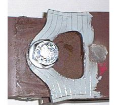
I guess you dont wanna end up having something like this ...
m_qeyjpd.jpg
 
It might be worth having a look in BS5400 and seeing if the values are less, with the same equations, or calling the SCI.

I'd be reluctant to accept the edge distance as it is, or even bother finding a way to evaluate the resistance on the reduced edge spacing. If it doesn't comply, it doesn't comply and whoever specified the hole location needs to budge or the beam needs to get bigger. I don't think this is an unreasonable position and wouldn't waste any more time on the issue or accept any further risk in my view as a designer.

 
My understanding of the need for minimum edge distances is that for load parallel to the edge in the steel, if there is too little edge distance the section can be prone to fracturing prematurely at the edge prior to attaining the necessary ductility demand in the member to mobilise the full net section ultimate strength (i.e. edge tearing).

For load perpendicular to the edge you are trying to prevent something similar to that occurring in the picture like Tommy385 posted.

The reason they often have different edge distance for cut or rolled sections is due to the roughness of the edge in rolled or cut plate and the effect this has on fracture mechanics, its also based on previous successful practice (i.e. never had an issue using these values, so why change).

Basically don't go less then the minimum code edge distances.
 
If all the client is looking for is a "yeah, it'll be ok", I would not give it to them. As Agent666 outlines above, there are reasons for the minimum edge distances that go beyond the bearing capacity. Unless you have an intimate understanding of the fracture mechanics, etc. behind those reasons, you can't say with any certainty that it is ok. I would clearly state that to the client/owner and put it back in their court to decide whether to leave it in violation of the code.

If they want to make it right, there are several ways that have been proposed above.
 
HR10 said:
If all the client is looking for is a "yeah, it'll be ok", I would not give it to them

That's where 'real engineering' kicks in...

Dik
 
"That's where 'real engineering' kicks in..."

If you're given the time and compensated for doing that 'real engineering', sure, go for it. However, without digging into the theory and research that went into setting those edge distance limits, I wouldn't give my approval to violate them.
 
HR10:

Two separate and often mutually exclusive issues...
 
The understanding of the engineering of the problem, and, the economics of providing a solution.

Dik
 
Status
Not open for further replies.

Part and Inventory Search

Sponsor