Continue to Site

Eng-Tips is the largest engineering community on the Internet

Intelligent Work Forums for Engineering Professionals

  • Congratulations waross on being selected by the Eng-Tips community for having the most helpful posts in the forums last week. Way to Go!

Hole on a symmetry line

Status
Not open for further replies.

Csaba Varga

Mechanical
Mar 4, 2021
3
ello!

I put a hole in a symmetric hollow section in symmetric plane. In a top view you can see, that the center of hole is on the symmetric line of the hollow section. What general tolerance concerns the deviation of hole’s center from symmetry line of hollow section? In the drawing is a general standard: ISO 2768-mK.

Thanks in adv.
Csaba

Picture in attachment
 
 https://files.engineering.com/getfile.aspx?folder=8ebb31f6-b914-4ed7-829a-6323ea3842b5&file=hole_on_symmetry_line.jpg
Replies continue below

Recommended for you

Csaba Varga,

I am an ASME guy, not ISO.

Holes on symmetry lines with positional location of zero, are one of the many reasons you should use positional tolerances.

True Position

--
JHG
 
Hello drawoh,

Thank for your reply.

Ok, i know that a position tolerance would be a solution to define it well.
But without position tolerance does it mean anything? Tolerated or not? If tolerated, how wide is the tolerance field?


Thanks in adv.
Csaba


Csaba Varga,

I do not know the policy of ISO. With the ASME Y14.5 standard, my understanding is that they are trying to lose the old plus/minus dimensioning for everything except features of size. If you control plus/minus dimensioning from a note on the drawing, you need to apply a dimension to be controlled by the note. If your hole sits on a centre-line, there is no dimension. You could try writing a note.

Positional tolerancing...
[ul]
[li]...specifies the correct shape of tolerance zone.[/li]
[li]...attaches the locational control of the hole to the specification of the hole. A [±][ ]tolerance attached to the dimension line, controls every hole attached to the line. These could be different holes requiring different tolerances.[/li]
[li]...connects the hole unambiguously to your datum features. The old [±][ ]dimensions can be weird and wonderful.[/li]
[/ul]

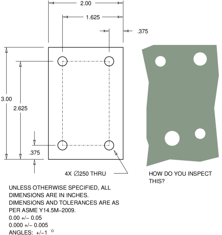
tolerances4x_my3k3w.png

This is my illustration of the Wrong Way.

--
JHG
 
drawoh said:
With the ASME Y14.5 standard, my understanding is that they are trying to lose the old plus/minus dimensioning for everything except features of size.

They've already lost it. It's been gone since at least the 2009 standard. Probably goes back farther. It's all the manufacturing facilities that are hanging onto it.

Csaba varga said:
In a top view you can see, that the center of hole is on the symmetric line of the hollow section.

Considering that the centerline only exists on the drawing, if you were to measure how centered the hole is on that centerline, how would you establish said centerline?

John Acosta, GDTP Senior Level
Manufacturing Engineering Tech
 
Still in the '2009 version.

2.6 (c) Direct Dimensioning. The maximum variation
between two features is controlled by the tolerance on
the dimension between the features; this results in the
least tolerance. In Fig. 2-4, illustration (c), the tolerance
between surfaces X and Y is ±0.05.
 
casaba

what is the hole for, is it for a bolt, subassembly or pin? or lighting hole the application will make a difference.
 
3DDave said:
Still in the '2009 version.

2.6 (c) Direct Dimensioning. The maximum variation
between two features is controlled by the tolerance on
the dimension between the features; this results in the
least tolerance. In Fig. 2-4, illustration (c), the tolerance
between surfaces X and Y is ±0.05.

Ugh. This makes me sad.
I guess you could resort to the note right after the paragraph that doesn't recommend this course of action but it still isn't a complete prohibition so, point taken.

John Acosta, GDTP Senior Level
Manufacturing Engineering Tech
 
I don't have the latest - in the case of a groove depth is that now a feature of size or is it practice to use profile of surface to control that?
 
3DDave said:
I don't have the latest - in the case of a groove depth is that now a feature of size or is it practice to use profile of surface to control that?

I don't know who you're asking but a groove depth is still not a feature of size. I don't see how it ever could be without a major overhaul on the definition of a feature of size. One of the benefits of a feature of size is that you can locate it with position (a control of the center of a feature) and modify it's location at MMC or LMC. If you think about it, what would be the MMC of a groove depth? Add material to the bottom and it's shallower, add material to the top and it's deeper. Profile of a surface is still the appropriate control for a groove depth.

John Acosta, GDTP Senior Level
Manufacturing Engineering Tech
 
powerhound, I took it from your post that direct dimensioning had been removed in the latest version from non feature of size use and wondered what the standard showed for this standard feature. The committee made irregular features of size out of thin air before, so they might have done so again.
 
Status
Not open for further replies.

Part and Inventory Search

Sponsor