Continue to Site

Eng-Tips is the largest engineering community on the Internet

Intelligent Work Forums for Engineering Professionals

  • Congratulations GregLocock on being selected by the Eng-Tips community for having the most helpful posts in the forums last week. Way to Go!

Horizontal Arching and Lateral Earth Pressures for Square Shaft Excavation Supported by Sheet Piles 1

Status
Not open for further replies.

palmahouse

Geotechnical
Jan 15, 2008
46
Is anyone aware of a rational (and simple) analysis approach for evaluating reduction (or increase) of theoretical average lateral earth pressures imposed on a retaining wall, relatively short in plan, with 90-degree "return" retaining walls that abut the wall ends?

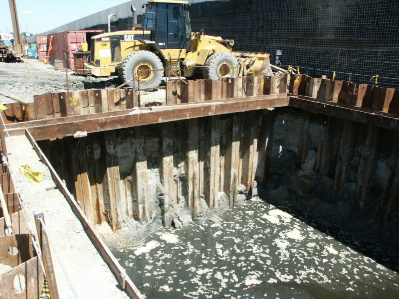
This is for temporary retention (shoring) of a square excavation with plan dimensions of about 15 by 15 feet and a depth of about 17 feet in loose (and dewatered) sand - to be supported by sheet piles either cantilevered or with internal bracing at the top of the excavation.

I think that on one hand, there are horizontal arching effects at the corners of the walls that may reduce the lateral earth pressures; but, and on the other hand, that there are structural stiffness (soil/structure interaction) effects at the corners that may raise the lateral earth pressures at the corners - to something higher than the active state (because the "return walls" stiffen the system). By horizontal arching, I am referring to the effects by which stress fields flow around the excavation boundary, like with vertical arching around tunnel excavations, that effectively reduce ground loads on the excavation boundary.

I plan to use the SHORING Suite software (by CivilTech) for my design (and use some judgement for the 3D effects that this 2D plane-strain model does not incorporate without implementing such judgement). I hope to perhaps reduce the lateral earth pressure profile in my design model because of horizontal arching and design a cantilevered system with no internal struts (assuming such a design is reliable).

I guess my summary question is this: How should I factor my plane-strain lateral earth pressure profile for this design?
 
Replies continue below

Recommended for you

As a bridge contractor, I designed and built a 3-wall waterfront cofferdam for construction of a large cast-in-place boat ramp, on driven timber piling. It was fairly wide, about 60 feet, with the two return walls about 40 feet each. It was dewatered approximately 12 feet deep. My recollection is having to add bracing as dewatering took place because the loading was so unpredictable (which revealed itself in unexpected deflection at odd places).

Bottom line, I would not cut corners on design of any 3-wall temporary sheet pile structure... just be conservative and watch during excavation to see if conservatism is good enough. A 4-wall geometry is much more stable.

[idea]
[r2d2]
 
PICT1266_f7lucl.jpg
For the four-sided case you describe, I would not use any reduction for arching at the corners of the sheeted pit. You describe the soil as loose. You want to cantilever 17' which is higher than I recommend. If your dewatering pump shuts down, your controlling design case could be where the water level is at subgrade inside the pit with water a few feet higher outside the pit. A 15' x 15' pit is very easy to internally brace with just a ring wale. In fact, the internal bracing could be part of your driving template. If you brace the SSP, its required length and section modulus should be much less than required for the 17' cantilever.


www.PeirceEngineering.com
 
Thank you both. I agree - we need to be conservative, brace across the top, and design for a contingency with inadequate dewatering. For seepage pressures, I am using 5 feet of head imposed on the ground side of the piles plus reduced passive resistance from lowered effective stresses, etc.

One more questions for you wise folks:

What do you recommend I use to model the strut spacing/tributary area)?

I think that each strut is taking one-half of the load imposed on the system (so, say 8 feet of tributary area for 16-foot-wide spacing between the beam), but, that the load per running foot of pile in plan is higher than I calculate with my plane-strain analysis. I think the loads are higher because arching increases the ground load at the corners. I think the lateral earth pressures near the corners approach an at-rest state, or about 5/3 times the loads imposed by the active state in my plane-strain analysis. So, I figure that perhaps I am closer to an at-rest state within about 4 feet from the corners and I preliminary propose modeling my "effective strut spacing" to about 10.6 feet (4 feet plus 4(5/3) feet = 10.6 feet). With this approach, if my design strut load from my active-state/plane-strain analysis is say 7.5 kips per running foot (still working on that), I would design for 7.5 x 10.6 = 79.5-kip compression strut loads (plus the lateral shear loads).
 
Thank you SlideRuleEra.

The layout is just like what is shown in PEinc's photographs with a 15- by 15-foot clear spacing between the beams. I suppose I should have called the bracing walers. I suppose that technically they are both struts and walers because they carry both axial compression and bending loads.

At any rate, I hope that helps you chime in on my previous questions and/or provide any additional comments.

I ended up using an "effective strut/waler spacing" of 11 feet from preliminary design and ended up with 75-kip or so reactions at the beams (for compressive axial loads). For this preliminary design, I modeled the distribution of the sum of the reactions on the beam (the distributed lateral load on the beams) with about 15 percent of the load imposed on the middle-third of the beam and then 42.5 percent imposed on the outer third portions of each side of the beams (because the corners are stiffer and should therefore take more of the load). My preliminary design calls for HP 14 x 89s.
 
Over many, many years and design-build jobs (both mine and others'), I have never, nor seen anyone else, distribute a wale load as you have described. Doing so, places less load toward the wales' mid-span and more toward the wale ends. This only decreases the bending moment in the wales and gives a less conservative design than by using a uniform, distributed wale load. If you are trying for stiffness at the corners, then you also need to design the wale to wale corner connections as moment connections. Doing this adds a lot of extra welding time and cost. Wale to wale connections are most often designed as pinned connections, free to rotate, with zero moment at the corners.

 
Thank you for your attention PEinc

I just wanted to chime in and demonstrate why I think my overall design is conservative.

So my computer program output (and hand-calculation) shows that the design brace load per running foot of wall is 6.5 kips per foot. For my distributed load profile on the beams, I have 6.52 kips per square foot acting at mid-span and about 9.2 kips per square feet acting at the ends (linearly increasing from mid-span to beam ends).

I did it that way because I think lateral earth pressures are higher at the corners than what my computer program and hand calculations tell me because the corners are stiffer, and because of that, the soil pressures approach an at-rest state there (as I describe in an earlier post).
 
Status
Not open for further replies.

Part and Inventory Search

Sponsor