Eng-Tips is the largest engineering community on the Internet

Intelligent Work Forums for Engineering Professionals

horizontal double wall pressure vessel 5

Status
Not open for further replies.

Pedro Losino

Mechanical
Feb 23, 2024
5
0
0
AR
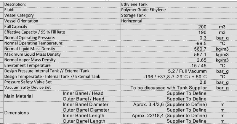
Good morning, I am starting the design of a double-walled horizontal pressure vessel to store ethylene. For temperature reasons, to avoid boiling of the ethylene, a double-walled container is proposed, with a vacuum in the annular space to act as an insulator. The design code needs to be ASME 8. Studying the code has raised doubts about the design process to follow. I understand that the internal container is designed by internal pressure, and the external container by external pressure, contemplating in the latter case a design pressure a little higher than atmospheric.
I appreciate any opinion on this, thank you!
 
Replies continue below

Recommended for you

Hmmmm,

I've had quite a bit of experience with similar systems for pipelines where it needed an metallic outer pipe in order to withstand the vacuum condition required for the insulation material to work effectively.

I would seriously question for something like a PV why you think this is required instead of the more standard PU foam, Foam glas or other solid insulation covered in some sort of thin skin (Aluminimum / stl or plastic. Might be twice as thick or more but who cares?

The issues tend to be about how you deign the outer shell for any leak or damage. as the design pressure is almost atmospheric, you need a bursting disc or similar to prevent over pressure of your second skin.

Testing issue then become problematic because none of the codes really cover it. There is an NFPA code which might do so, (designed for LNG, but its close) NFPA 59A I think.

For pipe it refers you back to B31.3 for testing which now requires a full pressure test of the annular piping.

If you design for "full" double containment it gets even worse.

So before you get into this too deep, have a big hard look at the issue and decide if you want to go down this route. I wouldn't if I really didn't have to.

Remember - More details = better answers
Also: If you get a response it's polite to respond to it.
 
thanks for your answer!
The original design was proposed by the client for whom we have to carry out the work.
Based on what I was informed, I understand that insulation can be achieved with very thick mineral wool, covered by aluminum plates as you mention.
The client clarified that according to their calculations (which I do not know), they could not avoid the evaporation of ethylene due to the loss of heat from the internal container, which is why they decided to insulate it with the annular space empty, and using a material called cryogenic perlite.
Beyond this, does the ASME VIII division 1 code cover the design of these tanks? According to the UG-19 section "special constructions" it seems so, but I have my doubts.
 
Mineral wool is ok, but for what I think are cryogenic vessels, you're much better off with PU foam or foam glas solid information.

Perlite is also good stuff and doesn't need to be vacuum located AFAIK to make it work effectively. Basically thousands of small beads poured into the top.

so its not "empty?" but filled with perlite?

Not a lot of this is making any sense at the moment to me....

Remember - More details = better answers
Also: If you get a response it's polite to respond to it.
 
expressing doubts to the client, one of his responses regarding the isolation method responded:
"the tank would not be externally insulated. It would only have perlite and vacuum in the annulus that exists between the internal and external tank"
We analyzed the possibility of PUF as an insulating material, with a thickness of 8" for cryogenic containers.
The idea is to propose alternatives to avoid the double-walled container, but I am also informing myself in case an agreement is not reached.
I appreciate your time to discuss this topic.
 
You are describing an industry standard cryogenic liquid storage tank design. The inner tank is a stainless steel Section VIII Div 1 pressure vessel. For the outer vessel I believe CGA 341 is the design code of interest. The outer shell is carbon steel and is designed for full internal vacuum.

Evacuated perlite is common for insulating the annular space, some vendors have also started to use what is essentially thin metallized mylar sheets wrapped in layers around the inner vessel to prevent radiation between the inner and outer shells.

No need to reinvent the wheel, these tanks are available commercially from various manufacturers. Sizes get up to about maybe 60,000-80,000 gallons (225-300 m3 for you fancy European types) before they start getting too be difficult to transport.
 
Thanks GBT, my thoughts exactly.
This is really no different than a commercial LH2 tank.
The LH2 tanks tend to use mylar in the vacuum space, N2, O2, and Ar all use perlite.
Baking these out an evacuating is a real task.
Beter to go with someone that knows these well.

= = = = = = = = = = = = = = = = = = = =
P.E. Metallurgy, consulting work welcomed
 
Are you sure?

CGA 341 looks like tanker truck design, so this volume look very big for road transport.

What pressure and temperature are we taking about here?

Remember - More details = better answers
Also: If you get a response it's polite to respond to it.
 
I haven't read it, but yes, from what I have seen vendors tend to reference CGA 341 for the outer shell design for stationary cryo containers. The stationary containers are the same basic design as a cargo container, I would guess whatever is in there for the outer shell design is still applicable.
 
Pedro,
This is so called vacuum insulated ethylene storage tank. I did purchase it more than 10 years ago for LNG project. The inner SS and outer CS vessels were designed per Div. 1. Nothing special. Vendor may offer cold-stretch for inner SS shell per Div. 1 App 44 but it is not mandatory. The annular space is packed with Perlite.
I visited the shop. What they told me was they vacuumed the annular space and vibrated the vessel, and poured in perlite to achieve certain density. It took days to complete the task. They did calculate the volume and knew exactly how much to put in. So stay with what vendor can provide as this is their expertise. Experience counts so using new material may not be good unless it is proven.
Two vendors we have used: Chart Inc in US and Cryeng in Australia.

 
Hello people, good morning.
The equipment is designed and manufactured because I am from Argentina and there are no possibilities of buying it abroad.
Regarding the posts, it has a capacity of 200 cubic meters (m3), 52834.4 gallons.
It has an estimated distance of 30 meters (98 feet) and a diameter of 3.6 meters (11.8 feet).
This must also be analyzed, how many mount type supports do you recommend? If there were 2, I can carry out the verification according to the Zick method. But I must also inform myself in case more supports are needed.
 
The design and manufacture of these tanks is fairly specialized and these manufacturers have been honing their craft for decades. I don't think designing one from scratch makes any sense at all. I am sure you can find a vendor who will be happy to quote you a tank, with delivery. Why do you say that there are no possibilities of buying abroad?
 
What's the design pressure of the inner vessel?

It's all about how you deal with the outer vessel skin.

I'm a little surprised you're not burying this. Gets away from the support issues. More than two is indeterminate. Search here for posts addressing these issues.

Remember - More details = better answers
Also: If you get a response it's polite to respond to it.
 
Captura_de_pantalla_2024-02-24_132750_ltrmxb.png

here, the design parameters.
30 connections are connected to it, so it must be on supports
In addition, a cold ethylene spray system is planned to maintain the temperature... it is a nice job to study
 
This is specialist equipment.
The inner vessel is designed per code. The outer Jacket is structural, and is not with in the U-Stamp scope of ASME VIII Div 1, but using the Div 1 rules for its design is reasonable.
With all the thermal expansion, design of the piping and supports can be tricky.
Much simpler and low risk just to use insulation.
 
Also why is design temp so low? That's lower than LNG?

30 connections???

Where?

Remember - More details = better answers
Also: If you get a response it's polite to respond to it.
 
You also need to know what your local laws and regulations are and how the regulator will approve this.

If something new then expect push back and many questions.

Remember - More details = better answers
Also: If you get a response it's polite to respond to it.
 
LittleInch said:
Also why is design temp so low? That's lower than LNG?
A lot of LNG equipment is purchased like this, rated down to -320F so that initial cooldown can be performed with LN2 before introducing the flammable product.
 
I can see it for LNG, but 100C below operating temperature is quite a lot.

Remember - More details = better answers
Also: If you get a response it's polite to respond to it.
 
Status
Not open for further replies.
Back
Top