Eng-Tips is the largest engineering community on the Internet

Intelligent Work Forums for Engineering Professionals

Horizontal Point Load on a Block Retaining Wall Barrier 1

Status
Not open for further replies.

Brad_S

Structural
Jun 14, 2018
15
0
0
US
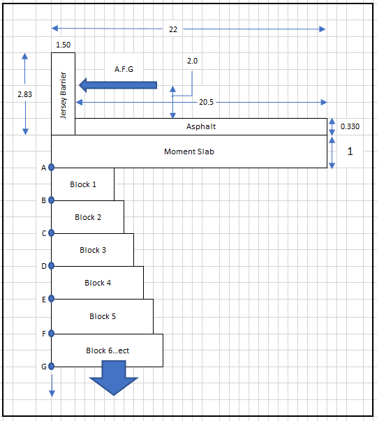
I am designing a segmented block retaining wall with a barrier on the top. The top of this retaining wall is a road and the barrier, according to TL-3, will have a 54K horizontal point load to account for the impact from a car. I have designed a spreadsheet that will calculate the bearing pressure if it were just a simple retaining wall with a simple back slope, but I am unsure how to handle the point load in the bearing calculation.

I currently have been attempting to add the vertical point load (Pveh) with the two other horizontal forces from the soils (Ps) and the surcharge loading (Pq) to get a total P. But this approach is giving me bearing pressures that are extremely high which makes me believe I am doing this wrong. If there is any code or material related to this, I would be more than willing to read but I have been unable to find anything so far.

Any help would be much appreciated!

Thank you!
 
Replies continue below

Recommended for you

I don't follow your nomenclature - what is Pveh, Ps, Pq, and P?
Care to post your free body diagram?

I've never done a segmented block retaining wall, but for a traditional cast in place concrete wall, that horizontal force would create a rotation.
That rotation would create a pressure under the toe of the foundation and an uplift at the heel of the foundation.
I would expect a 54k force to create a huge bearing pressure.
I would also expect that a segmental block wall isn't appropriate to stop a car.

What horizontal distance are you distributing the force over?
 
RetaingWall_pjmlqs.png


I apologize for not stating, those are the (Ps) and (Pq) are the pressures generated on the retaining wall by the soils and surcharge respectively. The active pressures acting upon the wall. I am not sure if you are to combine these pressures with a point load but I know when I calculated my Moment-Overturning and Moment-Resisting, that the vehicle point load was included. The retaining wall is not what is stopping a vehicle, the barrier wall sitting on top of the retaining wall is what shall be resisting the force.

I have not designed many retaining walls and I especially haven't designed any with a vehicular load with a horizontal impact load.

I attached an image with the current diagram of the situation. I don't have a free body diagram on the computer but I can upload my hand calculated FBD if the image is not enough.
 
We'll need a sketch of the cross section showing how and to what the barrier is anchored, how far away from the wall facing the barrier is, etc.

If you're looking at the bearing pressure below the reinforced backfill, there shouldn't be any increase in vertical bearing pressure due to a horizontal impact load.

Edit: I see you posted it while I was writing my post.
 
Considering that the blocks will be under where the highest pressure will be generated, and they are stiffer than the soil, virtually all the bearing force will go into the blocks and be carried to the bottom of the wall through them, the bearing pressure on the soil below the bottom block will be huge. You will likely need a concrete footing below the wall to distribute the load, which to me negates the advantage of using the blocks.

If you do use the blocks for aesthetic reasons, you will have to check their adequacy against crushing, especially at the interface between the blocks, if they are not solid. The Keystone blocks and similar ones are about half void space, you could exceed crushing strength of the concrete in the blocks.

The AASHTO LRFD bridge design spec. has some information on design in Section 13.
 

I have attached a quick calculation I did for the bearing wall. The calculations for just a simple retaining wall without the vehicle impact load was shown in the "Design Manual for Segmental Retaining Walls." I took these calculations and attempted to design them for this situation.

I am really not sure how the point load on the barrier will be transferred into the retaining wall which is my main area of concern.
 
I don't get it. Where does that HIGH vertical load come from when you only show a horizontal load AND DO NOT SAY IF ANY OF THESE UNITS (BARRIER AND BLOCKS) ARE SECURED TO EACH OTHER? Without the barrier secured to the wall below, you will depend on its long "beam" horizontal bending resistance and very little friction at its base. Also throw in the inertia of a barrier wall sitting on something, not tied down. That inertia for a long length of the barrier might be all you can work with. Since there has been double posting,my other posting comment indicated that if the barrier is a continuous concrete wall, adding anchorage to the top layer of blocks will significantly add to the inertia resistance to any horizontal impact to the barrier wall.
 
See the AASHTO LRFD bridge design spec., Section A13. According subsection A13.4.2, I think you could use the yield line failure length, Lc calculated in A13.3.1 as the distribution length.

If it was me, I would abandon the block wall and just do a concrete retaining wall that extends up to provide a barrier, eliminating the moment slab. Alternately, Keystone and other manufacturers provide help with designing block-faced MSE walls with integral barriers.
 
The barrier is designed for 54 K. The wall is designed for a 10 k impact force that is distributed along the length of the moment slab between expansion joints, not to exceed 30'.
 
Status
Not open for further replies.
Back
Top