Continue to Site

Eng-Tips is the largest engineering community on the Internet

Intelligent Work Forums for Engineering Professionals

  • Congratulations waross on being selected by the Eng-Tips community for having the most helpful posts in the forums last week. Way to Go!

How a restriction affects air flow at constant blower speed 5

Status
Not open for further replies.

PaulKraemer

Electrical
Jan 13, 2012
145
Hi,

I am working on a machine in which a blower running at a constant speed delivers air through an electric duct heater followed by an elbow and a length of straight duct into the top of a drying tunnel as illustrated below.
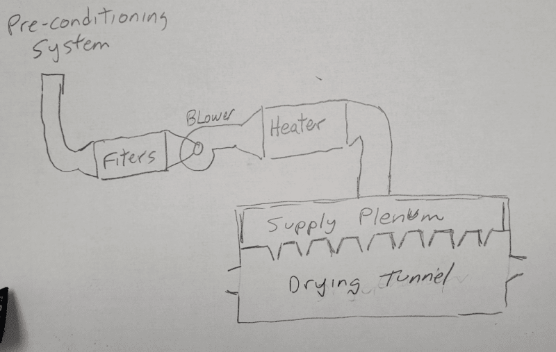
DryingTunnel_ofrpqf.png


When the heated air reaches the drying tunnel, it is delivered into a supply plenum that has eight adjustable air nozzles that allow the heated air to enter the drying tunnel.

Air nozzle openings are 9 inches long and can be adjusted anywhere between 1/16" to 3/8" wide. For a fixed blower RPM (assuming constant temperature of the air), I would assume that more CFM would be supplied to the drying when the air nozzle openings are set wider (closer to 3/8") as opposed to when they are set narrower (closer to 1/16"). While this seems to make sense intuitively, I am not completely confident. If anyone here can let me know if my assumption is correct, I would greatly appreciate it.

While I do not show it in my illustration. I also have an exhaust blower that removes the heated air from the bottom of the dryer. The exhaust blower is also set to run at a constant speed that is chosen so that the exhaust blower removes slightly more air than the supply blower delivers, making the drying tunnel slightly negative relative to its surrounding area.

Thanks in advance,
Paul
 
Replies continue below

Recommended for you

You are correct.

With a fan/blower the pressure differentials are below where one has to worry about compressibility; so incompressible.

q = CA(2gh[sub]L[/sub])[sup]1/2[/sup]

More flow area (A), more flow (q).

Good Luck,
Latexman
 
What is the diameter of your plenum?

So long as the square area is more than double your 9 x 3/8" area then your assumptions appear to be correct.

Also your blower needs to have enough capacity.

Remember - More details = better answers
Also: If you get a response it's polite to respond to it.
 
Opening the slots will increase flow rate (CFM) but will generally decrease velocity of the air leaving the slot nozzle. The purpose of the nozzles is to create velocity, in order to break though the boundary layer of stagnant air at the surface you are drying.
 
Hi Latexman and LittleInch,

Thank you for clearing that up. The plenum is rectangular, but its square area is many times the sum of my 9 x 3/8" openings.

I appreciate your help!

best regards,
Paul
 
Is the duct leading to the plenum large enough, it should be larger than the total area of you openings.
If you want to show yourself you can put a pressure gage on the plenum and then change the opening widths. If the pressure drops then then you have moved out on the blower curve toward greater flow.

= = = = = = = = = = = = = = = = = = = =
P.E. Metallurgy, consulting work welcomed
 
Check the Q-h curves from the blower vendors if they can provide variability in flow you are looking for. Axial fans have poorer variability on air flow compared to centrifugal blowers.
 
Hi EdStainless and georgeerghese,

Thank you for your responses. The duct that delivers the air into the supply plenum is 10" diameter (area 78.5 sq in). I had mistakenly said in my post that there were eight air nozzles, but there are actually ten of them. If this were all set as wide open as possible (0.375" wide x 9" long), ten of them would have a combined area of 33.75 sq in. While I do not currently have instrumentation in place to monitor the static pressure in the plenum itself, I do have instrumentation to monitor the static pressure in the 10" diameter duct just before it enters the plenum. I can easily see if (or how) this varies as I change the openings. Do you think this would provide useful information? Or it would it be much better if I can install the necessary instrumentation in the plenum itself?

With regard to george's comment, I have a centrifugal fan and I have attached the curves provided by the manufacturer. As you can see, this does not show the system curve. This is because I don't really know how to estimate what my system curve looks like. We have been using this type of blower for this type of application for quite some time, and we have always been able to get the drying effect we want by adjusting the speed of the blower and by adjusting the nozzles. We have always done this by feel, experience, and trial and error, but I am always trying to improve my understanding of the underlying dynamics from a more scientific perspective. I am frequently asked to estimate how much air we are moving at whatever blower speed we end up using. From the curves, I believe doing this requires knowledge of the static pressure the blower is working against. I believe this might require measurement of the static pressure both upstream and downstream of the blower, along with some math. New York Blower has some whitepapers on this that I'd like to re-read before asking specific questions about that here so as not to waste your time. I will re-read those and most likely post back here when I run into questions.

I really appreciate your help!

Best regards,
Paul


 https://files.engineering.com/getfile.aspx?folder=7983f1e2-f71e-4580-91eb-93d07e71cabe&file=2020-12567-001-AirCurveOPER.pdf
Ah,

Your OP though said the blower was working at constant speed and now you say it is an adjustable speed.

Big difference.

But yes, an easy way to estimate air usage is to measure differential pressure across your blower, but only if you're operating beyond 1500 cfm as otherwise the curve is too flat and the pressure difference too low.

And with a variable loss over the filter any readings are variable.

Is this thing pressure fed or just inlet from the open air? If so your blower PD looks quite low to me... but then what speed is that at? looks like you could go from 1780 rpm to 3360 so you really need to get the curves at different speeds from the vendor.

Remember - More details = better answers
Also: If you get a response it's polite to respond to it.
 
Hi LittleInch,

I did say in my OP that the blower was working at a constant speed, but I do use a variable speed drive. During initial production trials, we experiment with different supply and exhaust blower speeds until we find that we are drying the product within its target specifications. At this point, we set the blowers to always run at the fixed speeds that we decided work the best. This equipment is used in the production of pharmaceutical products (transdermal patches), so once operating parameters are established, validated, and sent to the FDA, no more changes are allowed, or else everything has to be re-validated. The particular customer that prompted my question is running both the supply blower and the similarly sized exhaust blower at 800 RPM.

They had been running this way for at least a month since we commissioned the machine, but they called yesterday and reported that now they are observing different drying conditions (and drying effects) with the same machine settings. They asked me if I could think of anything that could have changed that would have resulted in identical blower speeds and supply temperature setpoints resulting in different air flow to the dryer. Considering that a pre-conditioning system is in use that (if working properly) ensures constant static pressure, temperature, and relative humidity of the inbound air to our filters, the only things I could think of would be (1) if the filters had become clogged and/or (2) if the air nozzles in the dryer were set differently. Either of these things I figured could change the resistance/static pressure that the Supply Blower is working against.

I don't have instrumentation installed for measuring CFM, but I have a feeling it is quite a bit less than 1500 CPM. When I was last at the site, I think the customer was having another company install averaging pitot tubes in the inbound and outbound ductwork. The challenge initially was that the duct they had installed at the desired measurement location was of too large a diameter (in the opinion of the installer) to have any hope of being able to get an accurate measurement with the low air flows at which we operate. I will try to find out if this issue was resolved and if I can find out an air flow measurement.

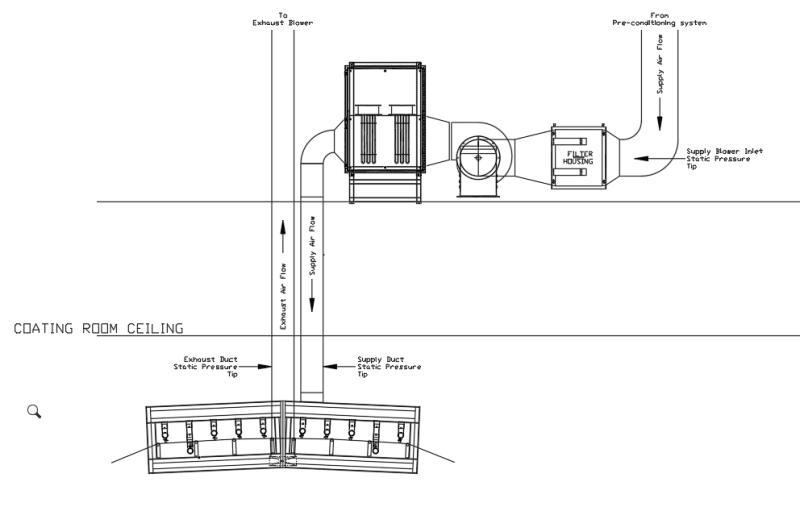
I will follow up when I get more information. In case it is useful, I have attached a more accurate diagram of our drying tunnel below. For the sake of clarity, I have only included the drying tunnel and associated air handling equipment and ductwork. The machine itself (not shown) is a web handling / web coating machine that applies a coating to a polyester film that is then conveyed through the dryer in order to dry the coating (which is a drug mixed with an adhesive, that eventually is converted into a transdermal patch).

DryingTunnel_oqnssy.png


I appreciate your help.

Best regards,
Paul
 
OK, makes more sense now.

The thing getting me is that you're dealing with incredibly low pressures and volumes here so any small normally inconsequential thing could make an big difference.

If I understand your data correctly, the blower is actually running at 800 rpm versus the 1700 on the graph, so you're looking I think at about 1 inch water column(!!) So if you have no DP measurement on the filter then even a small blockage will make a big difference.

You might be better to run the blowers a bit faster and very flow by use of a butterfly valve or similar.

Another variable is the drive itself. This is a very small motor and may not be reliable in terms of speed.

If your nozzles change and you're working in the flat zone, the blower pressure won't change so flow will decrease.

Remember - More details = better answers
Also: If you get a response it's polite to respond to it.
 
Since drying is sensitive to air flow, it would be good to have an airflow readout, else you'd be flying blind. Annubars are commonly used in low pressure air ducts-often used on combustion air ducts for forced draft fired heaters for air-fuel ratio control. Dont think there is a need to automate the air flow, since changes to flow probably occur slowly with time? Manual adjustments may be okay to keep air flow constant. As you say, air flow is also influenced by exhaust blower. Presume you have temp control on the heater.
Good you've got centrifugal blowers. Agreed, dp developed on this blower seems very low,even at 1755rpm.
 
Is the requirement linked to temp and drying time or were they dumb enough to put process variables into it?
Always certify results and not processes, any QA person will tell you this.
The critical variables look to be, DP across the filter, temp, humidity, flow in both lines, part line speed, and starting moisture of the parts. Each of these needs an acceptable operating range.


= = = = = = = = = = = = = = = = = = = =
P.E. Metallurgy, consulting work welcomed
 
Paul,

Another variable is inlet air conditions. Is the unit located in an area that provides constant inlet air conditions? Running with a small dP blower, a change in temp/humidity could have outsized impacts on blower performance.

Perhaps a lesson learned here that actually measuring the controlled variable (flow) is usually superior to relying on indirect indicators?
 
Status
Not open for further replies.

Part and Inventory Search

Sponsor