JamesPowell
Structural
- Sep 5, 2020
- 11
I am a final year student trying to study the behaviour of segmental columns subjected to biaxial cyclic loadings using Abaqus but am having some issues.
When I apply uniaxial cyclic loading it is fine and runs properly with correct results. However, when I try to apply biaxial cyclic loadings, I get some problems. Either the job doesn't run due to errors, or the results (hysteretic curves) look funny.
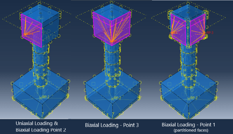
For the uniaxial loading I simply add a reference point near the loading block, apply a coupling constraint to the loading block face and reference point, and then apply the cyclic load amplitudes to the reference point as a boundary condition.
I have tried a few things for the biaxial loading, but none seem to work properly. I tried:
- Applying the x-axis and z-axis displacement amplitudes separately to the two adjacent faces of the loading block, each with its own reference point/coupling constraint. I had to partition the loading block and apply the coupling constraint to a smaller 'section' of the faces so that I am not applying 2 coupling constraints to the nodes in the corner.
- Applying the x-axis and z-axis displacement amplitudes as 2 boundary conditions to the same reference point/load block face (same as uniaxial but with 2 BC's on the RP). This seemed to "twist" the loading block as the x-axis loading was applied 'across' the face of the loading block and not 'into' it (I'm just hypothesising here).
- Applying the x-axis and z-axis displacement amplitudes as 2 boundary conditions to the same reference point, but applied the coupling constraint to the two adjacent load block faces.
These are shown in the image below. The 'points' on the image refer to the points given above. Nothing seems to give me the correct results and I am unsure of how I should proceed. Does anyone have any suggestions or experience with something similar? Thank you for any help!

