Continue to Site

Eng-Tips is the largest engineering community on the Internet

Intelligent Work Forums for Engineering Professionals

  • Congratulations KootK on being selected by the Eng-Tips community for having the most helpful posts in the forums last week. Way to Go!

How Close is too Close?

Status
Not open for further replies.

Mbrooke

Electrical
Nov 12, 2012
2,546
How close can a secondary fuse be near a transfomer's damage curve? How close to a primary fusing? Other secondary fuses? Is there a certain proportional ratio?

I have cases where E fuses touch a delta-wye damage curve and cases where a 140K fuses's "kink" comes close to the feeder fuse.

Obviously not likely to be put into practice- but as an extreme example:
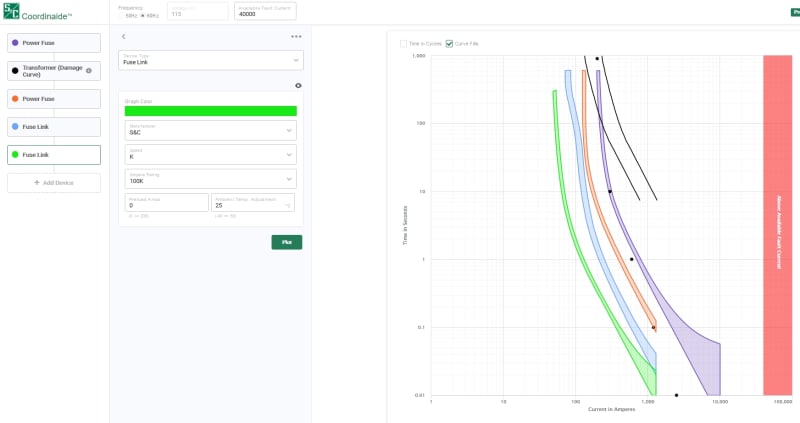
extreme_mz1ohq.jpg


Replies continue below

Recommended for you

If anyone is curious here is an example of what I would call good coordination:


1. 115kv SMD-2B slow fuse 150E

2. 28 MVA ONAN; 13.8kv secondary; delta-wye; 8% Z.

3. SM-5 slow fuse 400E

4. 140K fuse

5. 100K fuse

6. 65K fuse

7. 40K fuse

8. 25K fuse

I know in another thread it was mentioned that 4-8 were to close, but I'd argue that circuit impedance + arcing current limits the odds of miss-coordination.
 
I have feeling folks are thinking- why am I asking about secondary feeder fuses. To that I will just say allow me to introduce my magnum opus [2thumbsup]


fuse_1_f9at7y.jpg


fuse_2_wvzphf.jpg
 
"Maximum clearing time of the protecting link is no greater than 75% of the minimum melting time of the protected link"
-Electrical Distribution System Protection by Cooper Power System
 
This is what I was looking for. I also add a 25% setback for delta-wye transformers?
 
sure, but the fuse is going to cross over the damage curve somewhere, you can't follow that rule for all current range.

the more important thing you might have overlooked is shifting fuse curve for delta wye transformer specifically

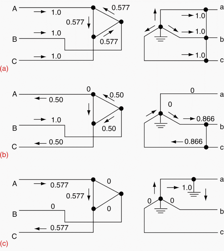
delta_wye_c7dwog.png


a SLG fault on the wye side will result in 0.57pu current flowing in the delta side. this effectively reduces the current as seen by the primary side fuse if you want to coordinate between primary and secondary side protection devices.

Similarly a LL fault on the wye side result in effectively more current on primary side, so the primary side fuse is sped up for coordination purpose.

Most TCC software will have options to shift the fuse curve to account for delta wye transformer.
 
sure, but the fuse is going to cross over the damage curve somewhere, you can't follow that rule for all current range.

Can you go into pore detail regarding this? Can the secondary fuse enter the damage curve at any point? Technically it should not if a High-Z feeder fault was to occur?


a SLG fault on the wye side will result in 0.57pu current flowing in the delta side. this effectively reduces the current as seen by the primary side fuse if you want to coordinate between primary and secondary side protection devices.

Similarly a LL fault on the wye side result in effectively more current on primary side, so the primary side fuse is sped up for coordination purpose.

I'm confused, don't you mean slowed down for a L-G fault since the fuse is seeing less current according to your graphic?

Do you know what multipliers these programs typically use? I'd like to know the math which in particular fascinates me this time around.

 
Thanks, I've been looking at that. Few questions come to me-

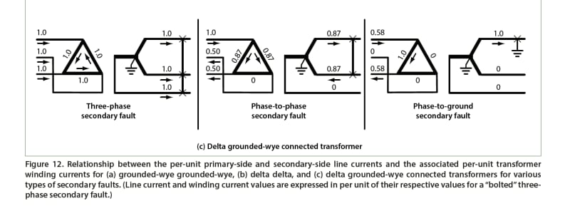
1) Why does table 2 list a per unit value of 1.15 for a phase-phase fault on a delta-wye trafo while Figure 12 lists 1.0, 5.0, 5.0 respectively? Where does 1.15 come from?


0001_iac6np.jpg


0002_ejucor.jpg


2) For a phase to phase fault the primary fuse subjected to 1.0pu will blow first, but what happens after operation with both 0.5pu fuses still remaining unblown? Wouldn't the fault still persist continuing to heat windings internally? Not sure how to take this scenario into account.
 
1)
phase to phase:. primary sees 1.15 more than secondary. This is the same as 1: 0.87 as shown in figure 12.

1.15 comes from 1:0.87

2)
good question
the 1.0 pu fuse opens and that's all. when this fuse opens, the two phases involved in the LL fault on the wye side will actually becomes same voltage and phase angle, although the short circuit still exist, since there is no difference in voltage to drive a fault. nothing trips anymore.

You can observe this for any delta wye transformer. Just open one phase on the delta draw the vectors, you will see all three windings are still energized, but only one winding get normal voltage, while the other two gets half voltage but and phase with each other.
 
1) OH! Any idea about the physics behind this?

2) Thanks! :)
 
Big help in understanding that phenomenon- thank you!


A bit of a different question. Can a secondary fuse's minimum melt curve partly enter a transformer's damage curve?

My inference: a 400E fuse (for example) optimistically starts to melt at 880 amps. A high impedance fault can load a phase above the transformer's secondary FLA but below the fuses minimum melting curve. Is this a realistic scenario? How well can a transformer tolerate unbalanced over-loading?
 
Status
Not open for further replies.

Part and Inventory Search

Sponsor