Continue to Site

Eng-Tips is the largest engineering community on the Internet

Intelligent Work Forums for Engineering Professionals

  • Congratulations waross on being selected by the Eng-Tips community for having the most helpful posts in the forums last week. Way to Go!

How do I calculate the deflection for a steel box beam filled in with concrete 1

Status
Not open for further replies.

Ash236

Civil/Environmental
Apr 15, 2016
3
SO my beam has a UDL applied so I've taken the deflection formula: ∆=(5*w*L^4)/(384*E*I)

I've calculated the second moment of area of the steel section and the second moment of area of the concrete area.
Im thinking I should plug them into the deflection equation like this: ∆=(5*w*L^4)/(384*((EI)steel+(EI)concrete))

Is this correct? If not then how would I go about completing a simple deflection calc?
 
Replies continue below

Recommended for you

Is the concrete going to act compositely with the steel? If so, you need to look at your transformed section properties - concrete in the tension zone won't help. Not sure how you'd get the steel and concrete to act compositely in this situation...maybe periodic through-bolts to engage the concrete?

If this is just a tube filled with concrete with no positive connection between the two, I think the concrete is just dead weight and doesn't help with your beam stiffness.
 
Sketch the actual shape and dimensions of the "steel box"?
Rebar inside the concrete inside the steel box? If so, what shape, size, and positions?
Was the steel "clean" and dry (or rough, or painted, or corroded, or polished, or corrugated)? How "good" is the steel-concrete interface?
Sketch the actual shape and thickness and alloy-grade of the steel box.

Depending on the proportions of both, and the quality of the bond between steel and concrete, the answer could "Yes, you can calculate the theoretical deflection." But the calculation might not mean anything in the real world. Or it might be "almost accurate" or "almost safe to use". Or not.
 
You have a fairly narrow window between a small deflection that may not engage the concrete, due to shrinkage, and the point where the concrete cracks and the stiffness is greatly reduced. You're not getting much of an increase in stiffness from plain concrete anyway, unless the tube is large with thin walls. If that's the case, reinforcing the concrete will help; making the tube composite with the reinforced concrete would increase the stiffness significantly.
 
And expanding on the above responses - no you can't use (EI(steel) + EI(concrete)) if they act compositely and the concrete cracks...which it probably will.


Check out Eng-Tips Forum's Policies here:
faq731-376
 
Personally I’d ignore the concrete (since I doubt the composite action and have no idea what will happen when it inevitably cracks). I would check deflection of the steel alone in that case.
 
To illustrate what everybody is saying:
Calculate the theoretical moment of inertia of a hollow figure 8 piece of "steel".
Now, if (when !) it bends, the "two" pieces of concrete will be split as if they have cracked apart.
But! If the upper and lower concrete solids are not stiff enough to prevent the two thin circles of steel from collapsing,
or if the concrete is firmly connected to the steel walls all the way around and is reinforced,
or if the concrete is properly reinforced but doesn't completely fill the upper steel,
or if the concrete is fragile and has no tension strength,
or if the upper circle of concrete supports the lower circle of steel against collapse but its surface is smooth and lubricated so it slides against the steel as it bends, you have six very, very different stress and yield cases.
And every case is correct. Theoretically.
 
One option would be to calculate the deflection using only the stiffer of the two sections.

Other option would be to transform one material to the other using the ratio of their elastic modulus, "n".

If you choose to consider the concrete, use its cracked moment of inertia.
 
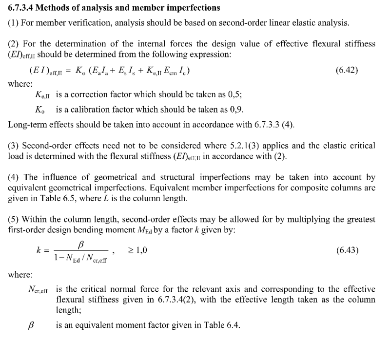
For a code based approach that correctly accounts for other effects like the influence of creep and cracking in the concrete fill, you should take a look at something like Eurocode 4. While some of the other methods mentioned above will give you a fully composite effective stiffness, they do not allow for expected concrete cracking or long term effects. Looking at just the bare steel behaviour is conservative, however creep and the concrete cracking would perhaps tend to increase the reduced real deflection you would see from the composite behaviour over time, in a similar manner to reinforced concrete design. So you just need to be aware of this for example if you have something being supported that might be sensitive to further deflections occurring over time.

EC4 has requirements for concrete filled composite members as concrete filled columns are fairly common and their behaviour is well understood. You would just be using it as a beam, i.e. no axial load and only bending. Alternatively the beam provisions can be used, whether the concrete is inside or beside a section has little bearing (though for axial load there is a confining effect in hollow sections which can improve the axial load capacity when the columns are not subject to buckling effects).

EC4 has the following relationship for determining the effective stiffness of composite columns, it stands to reason that a similar stiffness could be used for beam design for hollow filled sections, as noted there are 3 components, the steel section, any reinforcement and also the concrete which is reduced due to cracking effects. Effective stiffness is a linear sum of these components:-

Untitled_veacv1.png


You will note that there is no modular ratio being used, its because usually while the two materials work together, they are never perfectly composite, theres more complex relationship like slip/friction going on between the steel and concrete. This realtionship has I believe been derived based on calibration to real column behaviour from hundreds of historic tests on concrete filled hollow sections over time.

Note I believe EC4 was recently updated, so these relationships might have been tweaked. But it gives you an insight into the effects that need consideration at least.
 
Use the EC4 approach like Agent suggested. Designers Guide to EN 1994-2 should have some good background references as well if you get stuck on any of the clauses.
 
No one has asked what the point of the concrete is, & that's my first question. I can't see much purpose other than fire rating, and I think I would just look at the concrete as additional dead load.
 
Regarding fire rating (if it's at all relevant to the OP situation), in my experience you can achieve reasonable fire ratings with bare steel and concrete filling.

However, usually the thing that does not work is the mechanical transfer of load in the fire case. Meaning despite the member being fire rated by the presence of the concrete, you cannot get loads from incoming members into the core concrete without externally applied fire rating. I've reviewed a number of jobs where despite initially thinking that members would have no additional fire protection, they have ended up having to use intumescent coatings throughout to get it to work. Eurocode if I'm not mistaken requires you to transfer loads within a certain length of the member which is extremely limiting.
 
Concrete filling steel members is generally for deflection control or because you have local crushing forces or something that you're trying to deal with in a simple way. I've normally seen it in columns or posts though.

CAN/CSA S-16, the Canadian steel code, definitely touches on the strength of concrete filled pipes. Don't recall off the top of my head if it talks about deflection.
 
I looked into large-diameter concrete filled tubes for bridge foundations in high seismic regions, for which they are very well suited. They provide great ductility while maintaining their axial capacity. Presumably, the OP is aiming for the opposite - limiting deflection.

What I'm getting from the posts so far (anyone feel free to correct me if I'm wrong anywhere in here):

1) That plain concrete, not made composite with the tube by means of some sort of positive connection (something more than just bond), should be ignored for stiffness.

2) That reinforced concrete, not made composite as outlined above, can be counted for the stiffness as independently additive and combined based on strain compatibility.

3) Reinforced concrete made composite as outlined above can be considered a composite section.

What about plain concrete made composite?
 
Status
Not open for further replies.

Part and Inventory Search

Sponsor