Eng-Tips is the largest engineering community on the Internet

Intelligent Work Forums for Engineering Professionals

How do I find and represent an angled (oblique) cut in a tube? 1

Status
Not open for further replies.

Bettini84

Automotive
Apr 21, 2023
3
0
0
BR
Hello!

I need help on how to represent a cut on a tube in the proper way.
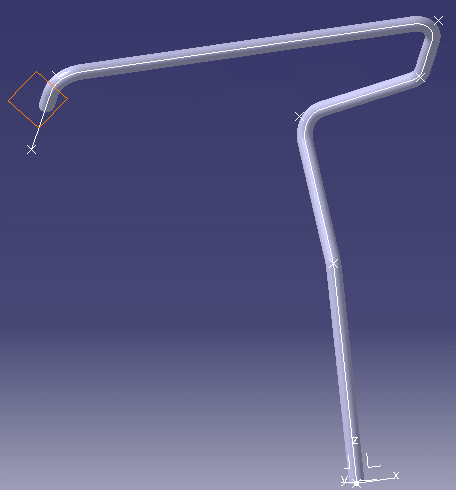
There are two parts involved. The first one is the truck rooftop, and the second one is a hanblebar (tube) for the driver to hold his hand and take a look at the cargo he is carrying. Like this one:
msedge_N9bWm4bUaP_iv9exy.png


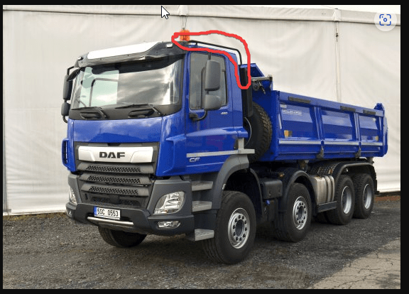
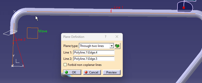
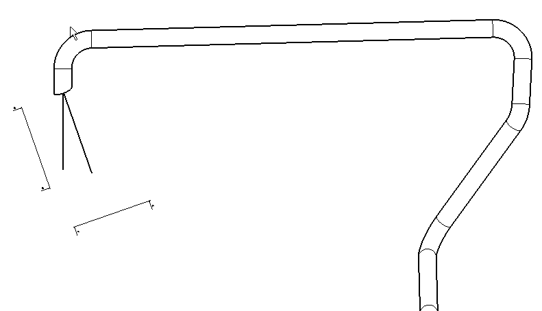
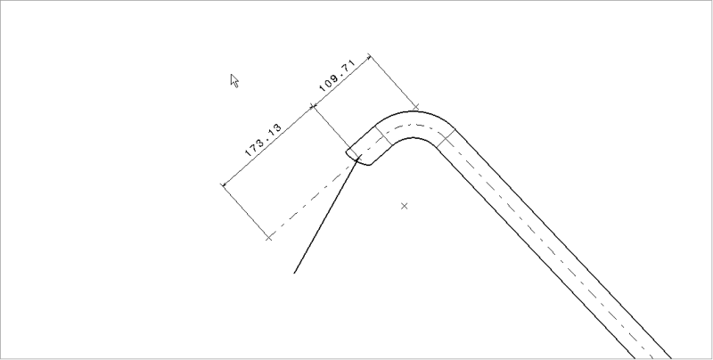
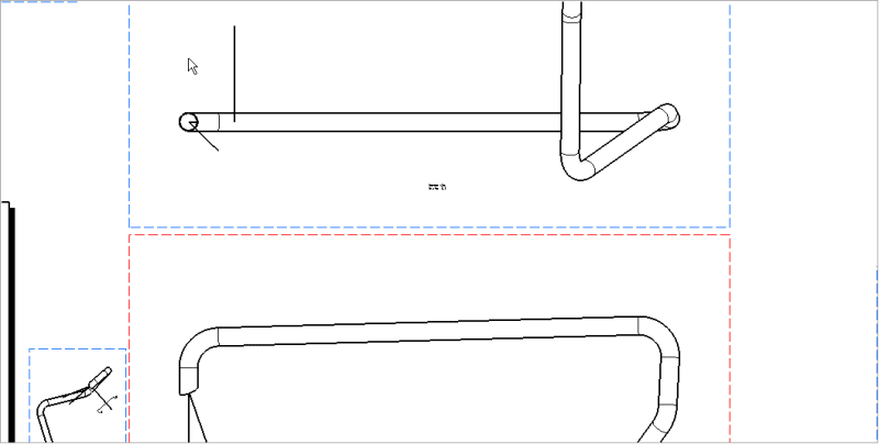
There is a cut on the tube that originated from a plane that was extracted from the roof of the truck.
CNEXT_ogP74RZ6Or_jt7swq.png


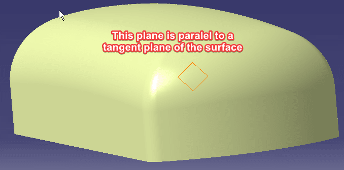
It is a built plane on the roof, but it is a dumb plane on the tube.
CNEXT_j5Ccs5PODK_o4tfdn.png


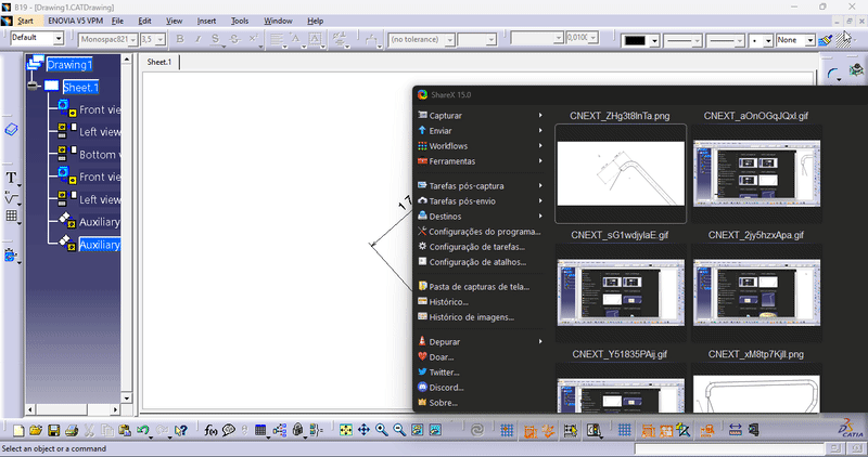
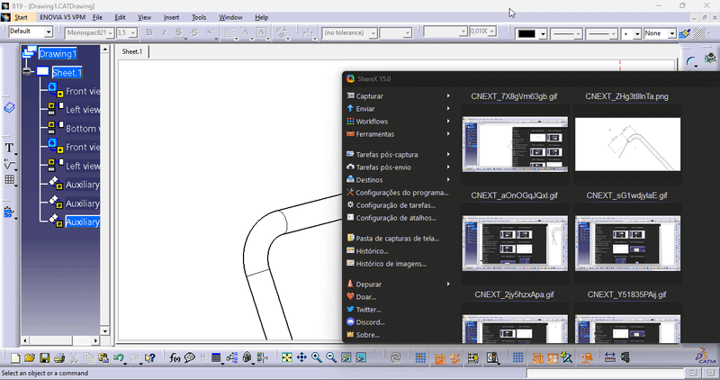
How do I rebuild the plane using the angles and axes of the tube's coordinate system? I'm asking this because I'm thinking of making 2 auxiliary views to show the real dimension of the cut.

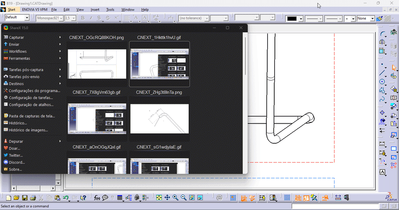
I made a video that might help you understand the issue a little bit better:

I also attached the files that I made at home that resemble the real files.
 
Replies continue below

Recommended for you

Step 1: Create a projection that shows the last bend as a planar - the two axes parallel to the viewing plane and showing the true angle between the last two segments.
Step 2: Create a projection from the Step 1 view showing that last segment of tube in a direct end view and the next to last segment heading off in some direction.
Step 3: Create a projection from Step 2 showing the cut in a flat-cut side view to show the true angle of the cut. You label the projection arrows with a dimension to the next to last segment.

Edit - alternatively, find the X,Y,Z location of the center point of the elliptical tube and and the unit vector normal to that in the tube X,Y,Z coordinate system. This will be more pleasing to the CMM operator and less pleasing to the tube fabricator who wants to know how much to turn and where to cut and at what angle.
 
Unless you want an expensive part and complex print you don't, you use a point chart to define the tube. You'd then draw a short reference line along the major axis of the ellipse and add the end points to define your cut on the chart. One isometric view, one auxiliary close-up of the cut (to clearly see the cut reference line), and a point chart - simple.
 
3DDave said:
Step 1: Create a projection that shows the last bend as a planar - the two axes parallel to the viewing plane and showing the true angle between the last two segments.
Like this?
CNEXT_Cupimqq6qO_ohz8ob.png

CNEXT_xM8tp7KjlI_huwuma.png


3DDave said:
Step 2: Create a projection from the Step 1 view showing that last segment of tube in a direct end view and the next to last segment heading off in some direction.
I don't understand it.
Is it like this below? I mean, a 90º projection of the first plane?
CNEXT_Y51835PAij_cu3sng.gif


3DDave said:
Step 3: Create a projection from Step 2 showing the cut in a flat-cut side view to show the true angle of the cut. You label the projection arrows with a dimension to the next to last segment.
Like this?
CNEXT_2jy5hzxApa_ti3eqq.gif


But now I need to relate this new plane to my original coordinate system for the tube.
I think I can do this:
1- auxiliary view from my front plane using the normal to the plane created on step 1.
CNEXT_sG1wdjylaE_botxif.gif


2- make another auxiliary view using the same normal in order to reveal the plane that was created on step 1.
CNEXT_aOnOGqJQxl_jmbhev.gif
 
In this view, I can show the true dimension from my last point (or the one before it) to the center of the elipse.
CNEXT_ZHg3t8lnTa_kpnjsl.png


3- I redo step 2:
CNEXT_7X8gVm63gb_nf8kli.gif


4- I redo step 3:
CNEXT_1Hkttk1hvU_iocdty.gif


Thank you very much, Dave!


---------------------------------------------//---------------------------//------------------

CWB1 said:
Unless you want an expensive part and complex print you don't, you use a point chart to define the tube. You'd then draw a short reference line along the major axis of the ellipse and add the end points to define your cut on the chart. One isometric view, one auxiliary close-up of the cut (to clearly see the cut reference line), and a point chart - simple.
I'm guessing you are Brazilian, so... Eu entendi o que você disse e é mais ou menos assim que está no desenho original. Eu vou mostrar os dois jeitos: esse que você citou e o jeito que o 3DDave explicou (que é a maneira certa de acordo com a norma). Aí o solicitante decide que caminho a seguir.
If you are not Brazilian, I understood what you just said, and it is more or less what they've done on the original drawing. I will show them both ways: the way you explained and the way 3DDave explained (which is the correct way to do it according to the standard). The person who requested the job will decide which path to follow.

Thank you very CWB1!
 
The second step is a plane that is normal to the pipe axis, showing the true diameter of the end of the tube. That would appear vertical in the second image.
 
3DDave said:
The second step is a plane that is normal to the pipe axis, showing the true diameter of the end of the tube. That would appear vertical in the second image.

It's more like this, then:
CNEXT_OGcRQ88KOH_ugpwyv.png


Therefore, Step 3 would be this:
CNEXT_lZxOF0w0jy_sfzbgr.gif


Is that right now?
 
Status
Not open for further replies.
Back
Top