Continue to Site

Eng-Tips is the largest engineering community on the Internet

Intelligent Work Forums for Engineering Professionals

  • Congratulations IDS on being selected by the Eng-Tips community for having the most helpful posts in the forums last week. Way to Go!

How do you model a 483-460-437V to 243V (6 phase double Y with interphase reactor) transformer? 1

Status
Not open for further replies.

bdn2004

Electrical
Jan 27, 2007
794
This info was on the Plant single line diagram.

This is a 348 kVA transformer whose output is connected to a 300 kW DC rectifier, that ouputs 250VDC to an overhead crane.

Why the double phase Y? And is it necessary to get more information on this transformer to properly model this for short circuit values etc?
Do you have to have the reactor size?
 
Replies continue below

Recommended for you

You are not giving much information to begin with but I'll share what I know.

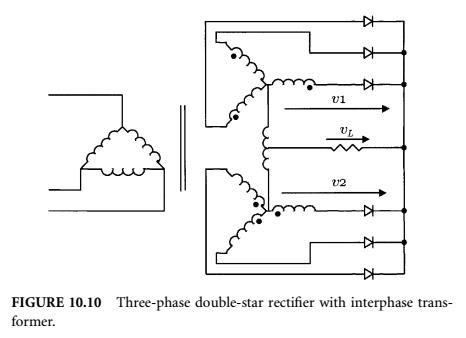
The double Y is there to give a 6 phase secondary output. One Y rotated 180º from the other (by inverting the polarity of each phase of the second Y winding) so you end up with a "6 pointed star" if you look at the secondary voltage phasors.

6-phase_double_star_fyzbwf.jpg


For starters, think about it as a 3-winding transformer (one HV and two LV). You will need the impedances, from the nameplate or the test report if available.

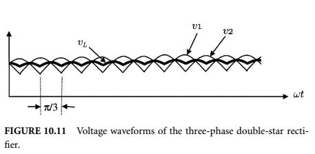
The interphase reactor, connected between the centers of the two Ys, is there to compensate (to some extent) the differences of voltages between both LV windings, wich helps with load sharing between them.

voltage_waveforms_hrqlp2.jpg


Thats the basics I know.

Now for a proper modelization of the circuit, including the interphase reactor, I recommend you Schaefer's book: Rectifier Circuits Theory and Design. Is a very good (old) book on the subject and has a chapter dedicated on how to reduce the multi-phase circuits into single-phase equivalents and the short circuit calculations.

Hope it helps.
 
Can you specify exactly for what purpose you have to model the transformer ?

- Contribution to SC-current in grid ?
- SC currents in case of a faulty rectifier ?
- current in cas of a short circui on the DC-line ?

For the first question (I assume that you are trying to do this from your information "This info was on the plant single line diagram") you can neglect the rectifier transformer. Beside a small magentizing current it will not contribute to SC-current on the grid side.


Status
Not open for further replies.

Part and Inventory Search

Sponsor