Continue to Site

Eng-Tips is the largest engineering community on the Internet

Intelligent Work Forums for Engineering Professionals

  • Congratulations KootK on being selected by the Eng-Tips community for having the most helpful posts in the forums last week. Way to Go!

How long is the center plane positional tolerance 1

Status
Not open for further replies.

sendithard

Industrial
Aug 26, 2021
166
Sorry for the bad pic, at work, don't have time to open saladworks.

I'm staring at this cylindrical part it has opposing cutouts on both sides and it is a feature of size...+/- .001 on the width size, so you get some bonus. A is the outside cylinder, B is top plane, C is some internal plane for clocking.

I'm not sure you need the Datum B for this callout, but that isn't my question at the moment.

My question is you collapse parallel planes until it hits the highs of these opposing surfaces and you make a midplane out of that. Great...well is the center plane tolerance zone simply the tallest two parallel objects you can fit into these cutouts, or is it 3.14159 mm tall...you get the idea. I don't see a definitive height this centerplane begins and ends at.

Thanks.
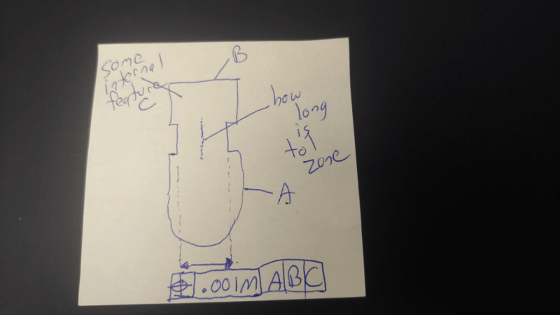
centerplane_ncxeug.png
 
Replies continue below

Recommended for you

sendithard,

This is a gray area in Y14.5 - the extent of a center plane (or an axis) is not fully defined. It is implied to be the segment that is between the actual bounding surfaces of the feature, but I'm not sure that it actually says that in the text anywhere. There are a few figures in the standard that show the axis or center plane of a feature with form or orientation error, but the specific details of the extent are not clear (to me, anyway).

Evan Janeshewski

Axymetrix Quality Engineering Inc.
 
Thanks for the reply...glad I was able to see this as you do.

Since I've read the standard front to back finally, I do remember this tidbit from 2009:

1.4 Fundamental Rules
(n) Unless otherwise specified, all tolerances apply for full depth, length, and width of the feature.

The legalese lawyer in me seems to think this should mean the largest planer collapsing parallel gage blocks that could fit inside the cutouts would determine the height check for the center plane. I always default to how you would build it on a surface plate and with hard gauges as that seems what GDT is premised upon.

 
Hi,

Interesting question!

I agree with Evan. It's not explicit.

I would say say that the axis or center plane goes on forever, because it is theoretical, but only needs to be controlled within the maximum area of the feature specified.

 
Dean,

I have told so many colleagues about your videos and I have learned so much from them.....thank you for putting the time in and getting creative with stuff like composite tolerances. Huge fan my friend! I watch every one of them.
 
I think the standard is pretty clear about it.
From Fundamental Rules (4.1 in Y14.5-2018):
"(o) UOS, all tolerances and datum features apply for full depth, length, and width of the feature."
The tolerance zone has to be as long as the actual feature is. Since this tolerance zone is where the center needs to fit, obviously the same applies to the center plane. It wouldn't make much sense to have a center plane shorter than the feature. If it's longer, it doesn't matter.
 
Burunduk,

Thanks for the Fundamentals reference - I thought that the extent was mentioned in the standard but I couldn't remember exactly where.

I would say that there is still a lot of ambiguity regarding the extent of the center plane, and the extent of the tolerance zone itself. The main issue is the definition of the depth, length, or width of the feature can become ambiguous on an as-produced part. Figure 3-1 in Y14.5-2018 (1-1 in 2009) is a good illustration of this, in the context of a cylindrical feature:

-The axis is shown as truncated at the tangent plane of the lower bounding surface. This would not make sense in every case, such as if the lower bounding surface was concave.
-The axis is also truncated at the upper bounding surface of the feature (the tilted top surface of the pin). This surface is drawn as perfectly flat and so the point of truncation is obvious. If the top surface was not perfectly flat, there would be uncertainty in exactly where to truncate the axis.

There are several other figures that show resolved geometry (axes and center planes) on different as-produced geometry. Figure 10-60 in 2018 shows the center plane of a slot, and a Position tolerance zone. The bounding surfaces of the slot are drawn as perfectly flat and perfectly parallel, so the extent of the center plane and tolerance zone are clear. It would not be so clear if these bounding surfaces had form and orientation variation. Figure 10-34 in 2018 shows a Position tolerance for the center plane of a tilted slot. The "full depth of the feature" rule could be interpreted in various ways in this case.

I would say that Y14.5 has not really tried to address the issue of feature extent and tolerance zone extent in a detailed way. We need to make assumptions when there is variation in the as-produced geometry, and we assume (or hope) that the magnitude of the discrepancies is not significant.


Evan Janeshewski

Axymetrix Quality Engineering Inc.
 
Evan,
I take the written fundamental rule as spelled out to be binding, whereas the figures are only illustrations and not the definition.
Then, the axis or center plane should reach far enough that there is no point on the feature beyond it. In other words, I should be able to find an actual intersection between a straight line passing through any point on the feature and normal to the axis or center plane derived from the feature, and the axis/center plane in question. I find any other interpretation as contradicting to the text of the fundamental rule.
 
If a flaw happens in part description and billions of observations don't notice a practical problem, does it make a difference?

For any nominal surface pair there is always the potential a component/element of one actual surface to not have a matching component/element on the other member of the pair. For that actual surface component/element there cannot be a midpoint or midplane so no control of the location of that actual surface component/element based on the midpoint or midplane makes any sense. Likewise any notion of "size" is also not sensible under those conditions.

 
When there is a local area in a feature of size with no opposed points there are indeed no center points in that area, however a center plane or center axis can still pass up to there since they depend only on the unrelated actual mating envelope. Likewise, you could still measure the size of the unrelated AME which is part of the size conformance evaluation under Rule#1. The swept spheres definition of size based on Y14.5.1M is also not affected.
 
If there's no "size" there's no unrelated actual mating envelope that applies. It's an extrapolation, a word not used in the standard. It would have been nice, but as Evan points out, and it was to him I was replying, they don't deal with the problem.
 
"Size" can still apply to the feature that has some opposed points missing since there are other types of size other than the actual local size, and the actual local size will apply to the portions where it's relevant in the same feature.

You may also want to check the latest addition to Rule#1 (5.8.1 in Y14.5-2018):

"(e) Where a portion of a regular feature of size has a localized area(s) that do not contain opposed points, the actual value of an individual distance at any cross section between the unrelated AME to a point on the surface may not violate the LMC limit. See Figure 5-9."
 
axym said:
The main issue is the definition of the depth, length, or width of the feature can become ambiguous on an as-produced part.

Evan,
I think you are consistent in your way of thinking. As you can see below on your replay on September 15, 2015 @14.20 the definition of the "distance" is ambiguous.

Is it the same idea? Are you having the same "complain" as you did 7 years ago?😉
I posted the thread discussed then as a refresher.
Nothing changed in the 2018 on this subject, as far as I can tell.

Evan said:
There are several problems with this definition (this discussion could fill another thread), but the main one for this thread is the idea of a "distance". This can't deal with non-opposed points. In the places where the points are not opposed, we can't define the actual local size. What is a distance when there is only one point?

 
Hi, sendithard:

The center of the position is called "derived median plane" per ASME Y14.5. Isn't length of this tolerance zone widths or heights of the slots?

Happy Thanksgiving!

Alex
 
Status
Not open for further replies.

Part and Inventory Search

Sponsor